Chapter 3 Install the Slim Profile InTouch
64
–
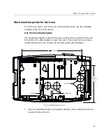
The top mounting screws must be 46 and 1/2 inches (1181 millimeters)
above the floor, for ADA compliance.
–
Use a level to ensure that the top of the template is horizontal to the floor.
Note:
If you are replacing a Series 4000 device, you can install the InTouch
on the same area of the wall but you cannot use the same screw holes.
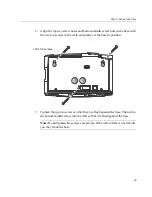
2. Mark the location of the mounting screw holes: Mark the top screw that is on
the far left, the top screw on the far right, and the single screw in the bottom
middle. (See the illustration in
“Step 3: Mount the base”
on page 68.)
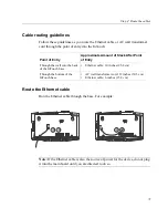
3. If you plan to run an Ethernet cable through the wall to enter the InTouch
from the back or through the bottom, use the template to mark the point of
entry. (See the illustrations in
“Route the Ethernet cable”
on page 71.)
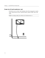
4. If you are installing the InTouch
near
an AC outlet, be sure the outlet is within
5 feet of the template. (See the illustration in
“Cable routing guidelines”
on
page 71.)
5. After you finish marking all entry points, screw holes, and so on, remove the
mounting template (or base) from the wall.
Содержание InTouch 9100 Slim Profile
Страница 4: ...Document Revision History Revision Release Date A June 2016 B December 2016 C March 2017 D April 2017 ...
Страница 9: ...Chapter 1 Before You Install the InTouch ...
Страница 21: ...Chapter 2 Install the Standard Model InTouch ...
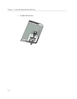
Страница 50: ...Chapter 2 Install the Standard Model InTouch 50 c Tighten both screws ...
Страница 60: ...Chapter 2 Install the Standard Model InTouch 60 ...
Страница 61: ...Chapter 3 Install the Slim Profile InTouch ...
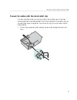
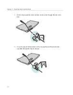
Страница 75: ...Step 6 Secure the cables with the strain relief clip 75 ...
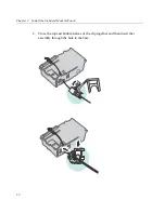
Страница 84: ...Chapter 3 Install the Slim Profile InTouch 84 ...
Страница 85: ...Chapter 4 Troubleshooting and Preventive Maintenance ...
Страница 94: ...Chapter 4 Troubleshooting and Preventive Maintenance 94 ...
Страница 95: ...Appendix A Replace a Series 4000 Device with the InTouch ...

