IK-12 NEXT
- 38 -
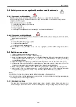
5.5 Ignition and flame adjustment
・
Adjust the gas pressure according to the Cutting Data. The data shows the pressure when all
the valves are open. Readjust the pressure after ignition.
■Flame adjustment method
1. Open the fuel gas valve 1/4
~
1/2 a tum, and light the torch with an igniter.
2. Then, open the preheating oxygen valve gradually until a white cone of the standard flame has
been obtained.
(
THE incandescent area should be uniform and about 5-6 mm (3/16-1/14
”) in length.
)
3. Open the jet oxygen valve fully. Readjust the flame if its condition has changed. A disorderly
flow of the jet oxygen will adversely affect the quality of the cutting surface. In such a case,
clean the tip with a suitable cleaning needle while the jet oxygen is flowing
4. Appropriate distance between the tip end and cutting surface.
・
Acetylene gas ················8-10mm
・
LPG gas ·······················5-8mm
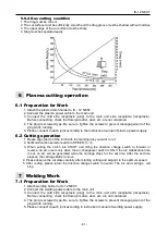
5.6 Cutting and piercing method
1
.
Cut in from the end of steel plate.
2
.
Pierce steel plate before cutting.
3
.
Drill a hole before cutting.
■
Piercing method
1
)
Ignite and adjust the flame.
2
)
Thoroughly preheat the cut-in point until it is white hot.
3
)
Open the cutting oxygen valve to pierce the steel plate. The tip should be about 15-20 mm from
the plate to prevent slag from splashing onto the tip and adhering there, which will shorten the
working life of the tip.
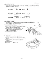
5.7 Procedures for starting cutting operation and
extinguishing the flame
1
.
Set Multi-function selector switch to SPEED
①~③
and adjust to the cutting start position. Ignite it
and adjust the flame.
2
.
Set the clutch in the START position to sufficiently heat the cutting start position.
3
.
After preheating, supply oxygen and simultaneously turn on the motor switch or the turning
direction switch to start cutting.
4. Carefully check the cutting condition, and control the cutting speed with the speed adjuster.
For the cutting speed, refer to the Cutting Data.
5
.
Extinguish the flame after cutting as follows:
1
)
Turn off the motor switch (or turning direction switch).
2
)
Close the cutting oxygen valve.
3
)
Close the preheating oxygen valve.
4
)
Close the fuel gas valve.
Содержание IK-12 NEXT
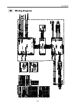
Страница 50: ...IK 12 NEXT 46 10 Wiring diagram...
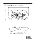
Страница 51: ...IK 12 NEXT 47 11 Assembly drawing of IK 12 NEXT 215mm 8 465inch 220mm 8 661inch 432mm 17 008inch...
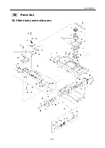
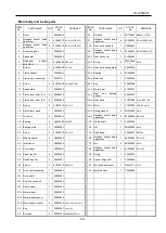
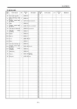
Страница 52: ...IK 12 NEXT 48 012 Parts list 12 1 Main body and inside parts...
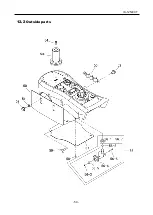
Страница 54: ...IK 12 NEXT 50 12 2 Outside parts...
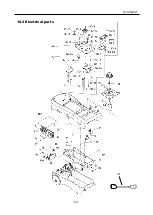
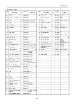
Страница 56: ...IK 12 NEXT 52 12 3 Electrical parts 103...

