background image

  IK-12  NEXT


- 7 - 

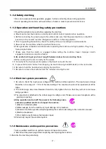
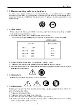
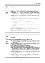
5. When you press the start button will cause the pilot arc immediately. Be sure to separate the body 

from the torch and cut it. 

6 .When touching the torch, wait until the surface of the torch cools and perform the work. 


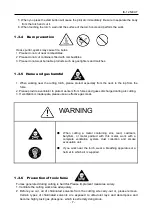
1.3.4


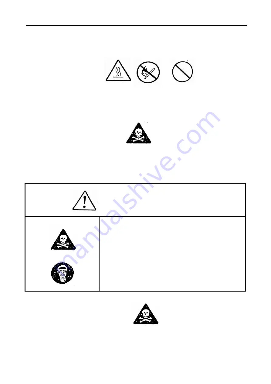
Burn prevention 


Heat, sputter, sparks may cause fire, burns. 
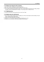
1. Please do not cut near combustibles. 
2. Please do not cut containers filled with combustibles. 
3. Please do not wear burnable products such as gas lighters and matches.


1.3.5


Hume and gas harmful 


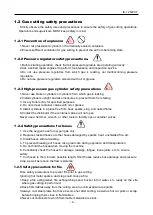
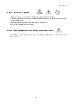
1. When  working  near  the  cutting  torch,  please  protect  especially  from  the  neck  to  the  top  from  the 

fume. 

2. Please provide a ventilator to protect workers from fumes and gases discharged during arc cutting. 
3. If ventilation is inadequate, please use an effective gas mask.


1.3.6


Prevention of toxic fume 

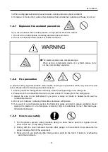
Fumes generated during cutting is harmful. Please implement measures surely. 
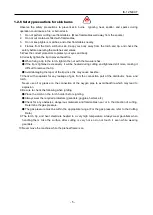
1. Ventilate the cutting work area adequately. 
2.  Before  you  cut,  all  of  chlorinated  solvents  from  the  cutting  site  carry-out  or,  please  remove. 

Certain  types  of  chlorinated  solvents  are  exposed  to  ultraviolet  rays  and  decompose  and 
become highly toxic gas phosgene, which is extremely dangerous. 


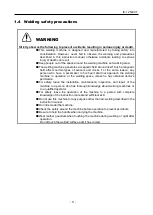
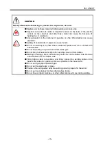
WARNING 


  When  cutting  a  metal  containing  zinc,  lead,  cadmium, 

beryllium,  or  metal  painted  with  this  metal,  work  with  a 
complete  ventilation  system,  dust  collection  and  smoke 
evacuation unit. 


● 

If  you  work  near  the  torch,  wear  a  breathing  apparatus  or  a 
helmet to which air is supplied.


Содержание IK-12 NEXT

Страница 1: ...OPERATION MANUAL KOIKE SANSO KOGYO CO LTD For every person who will be engaged in operation and maintenance supervision It is recommended to read through this manual before any operations so as to pe...

Страница 2: ...efer to it as necessary Do not use the machine carelessly without following the instructions in the manual Use the machine only after you have completely understood the contents of the manual If an ex...

Страница 3: ...perators must ground the equipment using the safety grounding terminal Pull out the power plug from the outlet Operators must unplug the power plug from the outlet when a failure occurs or when there...

Страница 4: ...fety Measures before Starting Work 37 5 5 Ignition and flame adjustment 38 5 6 Cutting and piercing method 38 5 7 Procedures for starting cutting operation and extinguishing the flame 38 5 8 Safety me...

Страница 5: ...d fully understand the following important safety information 1 1 1 Machine safety 1 The machine casing is mainly made of aluminum alloy to reduce weight For this reason be careful not to drop a heavy...

Страница 6: ...ouch the rail 11 To prevent the torch holder from dropping fix it with the wing bolt BS 6x22 on the torch slide 12 Be sure to hold the handle when carrying the machine 13 Be sure to remove the machine...

Страница 7: ...ockimpact at carriage or if mounting screw of handle is loose 1 1 7 Machine noise 1 Volume of at the time of driving the machine is less than 70dB 1 1 8 About external environment 1 Never use the mach...

Страница 8: ...ee from heat sparks slag and naked flame 6 Contact the distributor if the container valves will not open Never use a hammer wrench or other tools to forcibly open container valves 1 2 4 Safety precaut...

Страница 9: ...tened still more making it difficult to remove the tip Avoid damaging the taper of the tip since this may cause backfire 7 Check with soapsuds for any leakage of gas from the connection part of the di...

Страница 10: ...e damaged shading plate broken glasses goggles helmet 3 Please warn other people in the workplace to wear eyeglasses goggles helmets 4 We recommend that you can install protective screens and curtains...

Страница 11: ...ilator to protect workers from fumes and gases discharged during arc cutting 3 If ventilation is inadequate please use an effective gas mask 1 3 6 Prevention of toxic fume Fumes generated during cutti...

Страница 12: ...st 10 m away from the cutting place 3 Always be sure to cool beforehand if you place a newly cut metal or heated metal near the combustible material 4 Do not cut containers containing flammable substa...

Страница 13: ...rly If you see damaged parts such as fatigue and wear please replace it immediately 1 3 11 Ground of cutting surface plate 1 Make sure to connect the ground cable directly from the cutting member or s...

Страница 14: ...ure or cause serious accidents By the skilled repair technician repair please check 3 Never use pressure regulators that have leaks or malfunctions 4 Do not use regulators with oil or grease 1 3 15 Sa...

Страница 15: ...acemaker in his heart shall not approach the welding machine in operation or the welding space unless he has obtained doctor s permission For safety leave the installation maintenance inspection and r...

Страница 16: ...machine with the welding machine case or coser removed Be sure to cover the input and output terminals before use Do not use broken or wet gauntlets Never fail to use a life line when working in high...

Страница 17: ...s high wear a noise proofing protector CAUTION Use protective gear to protect you and others from fumes and gas generated by welding Welding generates fumes and gas Inhalation of such fumes and gas ca...

Страница 18: ...as cylinders only for specified purposes DO not apply oil or grease to the valve on gas cylinders When the valve on gas cylinders is hard to open contact the dealer CAUTION Strictly observe the follow...

Страница 19: ...tered spatters will be in contact with inflammables Do not do welding in a place near inflammable gas Do not bring hot base metal right after welding close to inflammables Welding on ceilings floors a...

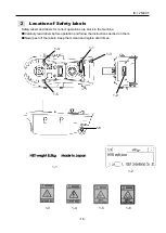
Страница 20: ...and labels for correct operations are stuck to the machine Carefully read labels before operation and follow the instructions decried on them Never peel off the labels Keep them clean and legible at a...

Страница 21: ...on 5 Pressing a button instantly switches to slow travel to help to prevent uncut material being left at the start and finish ends when cutting thick material 6 The incorporated arc coupling function...

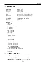
Страница 22: ...ail 1 8M 2 Circle rail 3 Circle cutting attachment 4 S 100 torch set 5 S 200 torch set 6 SP 100 torch set 7 SP 200 torch set 8 SR 100 torch set 9 SR 200 torch set 10 SPR 100 torch set 11 SPR 200 torch...

Страница 23: ...isk of short circuit due to tearing of insulation covering Kindly weld below the rated current and usage rate of torch to prevent dielectric breakdown due to overheating Kindly place power cable and t...

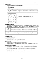
Страница 24: ...Treatment position When the switch ot the welding power supply which is to be connected to the welding machine is set in the Self Holding or Crater Treatment position the welding arc will not stop ev...

Страница 25: ...WU 3R make sure Turn Off the Power When the power is on if it gets connected there is a possibility of failure 3 Operation panel The detail is shown below 4 Heat insulating plate It prevents heat from...

Страница 26: ...input voltage within 10 for power supply input to input plug Kindly use input voltage in the range of AC100V AC240V There is risk of short circuit due to failure of printed board on operation panel In...

Страница 27: ...rection selection switch has been operated while this switch is flipped to the MANUAL side turn the power OFF and back ON Multi function selector switch This switch is used to select each parameter an...

Страница 28: ...detecting welding current 012 Encoder selection error 013 Unit configuration unsuitable error 014 Weld movement distance during tack operation error 016 Servo driver error This is an error that occurs...

Страница 29: ...of the carriage can be changed by turning the volume switch while the carriage is stopped and while it is traveling To increase the speed turn it clockwise and to decrease the speed turn it countercl...

Страница 30: ...it is traveling To increase the speed turn it clockwise and to decrease the speed turn it counterclockwise Operation Panel Indication Digital Display Setting Range Default Value 40 2400 mm min 2400mm...

Страница 31: ...ING SPEED starts weaving as an independent operation No arc is generated in independent operation This is not used when no weaving unit is connected When WU 3R connected Operation Panel Indication Dig...

Страница 32: ...rts weaving as an independent operation No arc is generated in independent operation This is not used when no weaving unit is connected When WU 3R connected Operation Panel Indication Digital Display...

Страница 33: ...e carriage is stopped and the multi function selector switch is set to TIMER LEFT starts weaving as an independent operation No arc is generated in independent operation This is not used when no weavi...

Страница 34: ...r the arc stabilization time is in progress This may cause the carriage to operate unexpectedly In order to weld for the arc stabilization time with the initial arc current an initial arc setting has...

Страница 35: ...ting is self latching crater filling supported If the value above is set and the arc is frequently interrupted set the value to 0 1 In this case the signal will remain in the ON state up until the arc...

Страница 36: ...h respect to the speed indicated at the digital display Actual speed speed displayed This parameter value Not used Model Selection Setting 0 WH MULTI NEXT 1 IK 12NEXT After setting this parameter swit...

Страница 37: ...omes like the following time chart Example1 Parameter settings Central torch stop time 0sec Left torch stop time 0sec Right torch stop time 0sec Weaving swing width 10mm 0 39inch Example2 Parameter se...

Страница 38: ...IK 12 NEXT 34 Weaving swing width swing speed is the numerical value of at a distance 100mm from the center of rotation Rotation center Swing speed Swing width Origin position...

Страница 39: ...rm Pipe arm 500L Pipe arm 500L Arm holder Distributor Double distribution with valves Triple distribution with valves Torch holder Profiling system Profiling system Bevel attachment For cutting V For...

Страница 40: ...tal receptacle is fitted with screws Be sure to tighten the screws in order to prevent the plug coming out while the unit is traveling When turning on the power supply after turning off the unit body...

Страница 41: ...n Use a power outlet with an opening to receive the ground pin 5 4 2 Operating the direction selection switch The direction selection switch is used to switch between forward and reverse travel The ne...

Страница 42: ...steel plate before cutting 3 Drill a hole before cutting Piercing method 1 Ignite and adjust the flame 2 Thoroughly preheat the cut in point until it is white hot 3 Open the cutting oxygen valve to pi...

Страница 43: ...lightly open the preheating oxygen valve and then ignite the oxygen with an ignition lighter Then fully open the gas valve and make the flame neutral by controlling the preheating oxygen 4 Adjust the...

Страница 44: ...2 Attach pivot pin and weight to radius bar Please attach weight as close to the center as possible 3 Free the guide wheel and pull the machine so that it describes a natural arc and tighten the guid...

Страница 45: ...cut 2 Set Multi function selector switch to SPEED 3 When putting the clutch into START and tilting the direction change switch to forward or reverse an arc occurs only when the arc changeover switch...

Страница 46: ...able to use this unit in the best condition at all times 8 1 Daily Inspections 1 Wipe off the dirt on the unit with a clean cloth especially the pipe arm key slots and rack parts 2 Lubricate the axles...

Страница 47: ...continuty check by tester while electric supply is turned OFF Since above mentioned 2 and 3 checking are to be carried out while control power supply is ON professional engineer having enough knowledg...

Страница 48: ...t carriage travel fails to stop when the direction selection switch is returned to neutral during travel 1 Printed circuit board failure 9 The travel speed of the carriage does not change when the CRE...

Страница 49: ...e lubrication shortage 15 High level of vibration or noise 1 Foreign object trapped in the gears 2 Wear of gears 3 Motor failure 4 Speed reducer failure 16 Knocking occurs 1 Gear wear 2 Play between t...

Страница 50: ...IK 12 NEXT 46 10 Wiring diagram...

Страница 51: ...IK 12 NEXT 47 11 Assembly drawing of IK 12 NEXT 215mm 8 465inch 220mm 8 661inch 432mm 17 008inch...

Страница 52: ...IK 12 NEXT 48 012 Parts list 12 1 Main body and inside parts...

Страница 53: ...lever shim 0 5 1 20506245 32 10 Gear head 1 61007942 IG 43 KS5 1 49 15 Screw 4 6C500510 SF 5 12 32 11 Motor 1 61007939 With the pinion 16 Clutch lever base 1 20506242 32 12 Spring washer 4 6D510040 WS...

Страница 54: ...IK 12 NEXT 50 12 2 Outside parts...

Страница 55: ...54 Hexagon socket head cap screw 4 6C450515 BC 5 15 WS WF 55 Chip support assembly 1 60035003 Accessories 56 Universal wheel assembly 1 20506418 56 1 Spacer 1 20506235 56 2 Washer 1 60030211 56 3 U n...

Страница 56: ...IK 12 NEXT 52 12 3 Electrical parts 103...

Страница 57: ...20506481 MD CN6 Receptacle assembly 80 12 Receptacle assembly 1 20506464 Harness plaiting A Harness plaiting C 99 Harness plaiting D 4P 4P 1 20506478 MD CN3 SW CN2 Receptacle 1 64000510 NCS 255 R squ...

Страница 58: ...750 680 102 D7 HIGH SPEED For Acetylene PLATE THICKNESS mm TIP SIZE CUTTING SPEED mm min PRESSURE kg c Mpa FLOW RATE H OXYGEN ACETYLENE CUTTING OXYGEN PREHEATING OXYGEN ACETYLEN 5 10 0 750 680 7 0 0...

Страница 59: ...0 1 180 310 10 15 1 625 550 0 2 0 02 2 400 1 180 310 15 30 2 550 475 0 25 0 025 3 600 1 370 360 30 40 3 475 425 0 25 0 025 4 800 1 370 360 40 50 4 425 350 0 3 0 03 5 600 1 860 490 106 D7 HIGH SPEED Fo...

Страница 60: ...IK 12 NEXT OPERATION MANUAL Date of issue Sep 2018 2nd Nov 2018 3rd Dec 2018 KOIKE SANSO KOGYO CO LTD Printed in Japan...

Отзывы: