- 33 -
- 33 -
59
58
57
56
13
Engine assembly
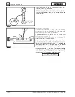
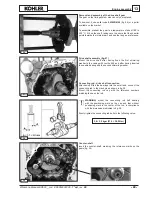
Removal and assembly of the drive shaft gear
The gear on the timing system side can only be replaced.
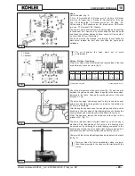
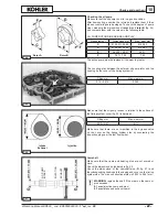
To demount it, use puller code
00365R0100
(fig. 56) or a puller
available on the market.
To assemble, preheat the gear to a temperature of about 180 to
200 °C, fit it on the shaft, taking care to ensure that the chamfer
points towards the internal part, and use the tang as a reference.
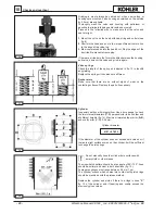
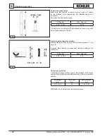
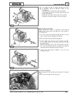
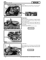
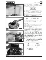
Drive shaft assembly (fig. 57)
Mount the drive shaft after having fixed the first shimming
washer to the casing with Loctite 648 and after having inserted
the needle bearing and the second shimming washer.
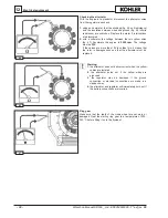
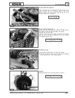
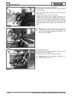
Connecting rod - drive shaft connection
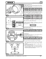
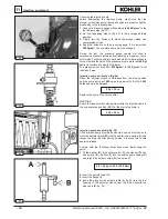
After having fitted the bearings into the small end, connect the
connecting rod to the crank pin as shown in fig. 58.
Mount the connecting rod cap with the reference numbers
matching those on the rod.
WARNING:
mount the connecting rod half bearing
with the positioning mark on the cap and that without
positioning mark in the center of the rod, in compliance
with the dimensions indicated in fig. 58.
Evenly tighten the connecting rod bolts to the following value:
3,8 ÷ 3,9 kgm (37,3 ÷ 38,2 Nm)
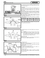
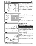
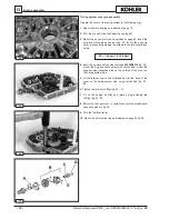
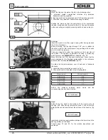
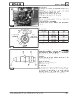
Counter-shaft
Insert the counter-shaft, matching the reference marks on the
gears (fig. 59).
Workshop Manual KD500 _ cod. ED0053029390 -
1° ed
_rev.
00
Содержание KD 500
Страница 1: ...KD 500 WORKSHOP MANUAL...
Страница 6: ...6 Index Workshop Manual KD500 _ cod ED0053029390 1 ed_rev 00...

