- 19 -
- 19 -
11
10
9
8
10
ØA
ØB
ØC1
ØC2
ØD1
ØD2
ØE(*) ØF1
ØF2
G
13
÷
13,01
13,025
÷
13,037
40,13
÷
40,145
35,13
÷
35,145
40
÷
40,025
35
÷
35,025
7
÷
7,01
6,96
÷
6,97
6,945
÷
6,995
0,8
÷
1
CHECKS AND OVERHAUL
Head
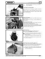
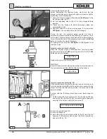
Parts indicated in fig. 8.
1.
Nut -
2.
Nut with ball -
3.
Rocker arm -
4.
Cotters -
5.
Rocker
arm stud -
6.
Upper cap -
7.
Spring -
8.
Air-relief valve -
9.
Lower
cap -
10.
Valve guide -
11.
Rocker arm cover -
12.
Head -
13.
Valve housing -
14.
Exhaust valve -
15.
Intake valve -
16.
Rocker
arm rod -
17.
Camshaft -
18.
Tappets.
The head is made of aluminium with valve guides and housings
in faced cast iron. Remove any carbon deposits from the head
and check the cylinder bearing surface. Level it off to a depth of
no more than 0.3 mm if deformed.
The head must not be cracked or deformed. If such faults are
discovered, replace the part after consulting the spare parts
catalogue.
Do not demount the head when hot to avoid
deformations.
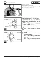
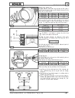
Valves - Guides - Housings
Clean the valves with a metal brush and replace them if the tops
are deformed, cracked or worn (fig. 9).
1 = intake
2 = exhaust
(*) with guide mounted.
measurements in mm
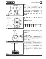
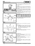
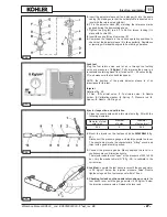
Check the dimensions of the valve stem (fig. 10) and the play
between the guide and valve. Ream the guide to the dimensions
indicated in the table. Change the guide and valve if the play
exceeds 0.1 mm.
The valve housings will always need to be ground when new
guides are mounted. Valve guides oversized on the outside by
0.10 mm are available.
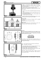
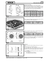
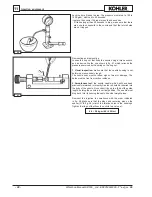
After the engine has been used for a lengthy period of time, valve
knocking in their housings at high temperatures will harden the
housing tracks and make manual milling difficult to carry out.
When this happens, remove the hardened surface layer with a
grinder at 45° (Fig. 11).
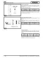
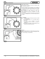
The valve retention track will widen when the valve housing is
machined. Final adaptation of the valve in the housing must
be carried out by smearing fine grain lapping compound in the
housing and turning the valve with a light pressure and with an
alternate movement until the surfaces bed perfectly (fig. 12).
Comply with the valve embedding values as indicated in the table
(
G
, fig. 9).
Warning: when the valve embedding values are lower
than those prescribed, the valves could interfere with the
piston.
Workshop Manual KD500 _ cod. ED0053029390 -
1° ed
_rev.
00
Содержание KD 500
Страница 1: ...KD 500 WORKSHOP MANUAL...
Страница 6: ...6 Index Workshop Manual KD500 _ cod ED0053029390 1 ed_rev 00...


