background image

MDP-621/641/640  

Chapter 

Operation manual                        


Plotter operation 


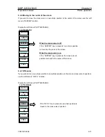
(c) Setting the mark shape 

Press the “SHAPE” key to display the SHAPE settings box. Select the shape of the mark you 

want to search for. 

7 ALL

SHAPE


Use the up / down key to set the shape. 
The mark shape that has been set is displayed
in the soft menu. 
If ALL is selected, all shapes will be assigned
for the search. 


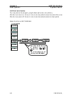
(d) Setting the comment 

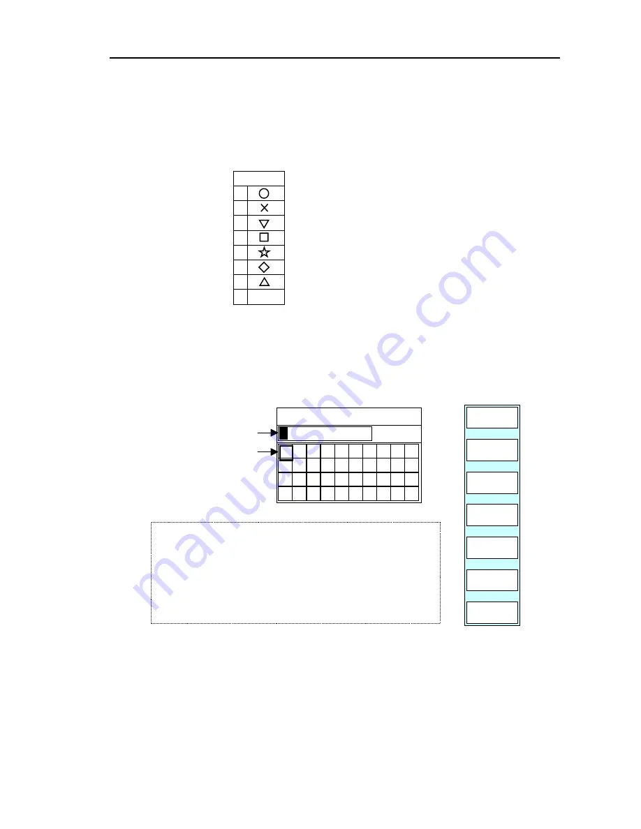
Press the “CMNT” key. The following soft menu and comment settings box are displayed. 

Enter the comment you want to search for. If the ”ENTER” key is pressed, the entry is 

completed. 

GOTO/WPT SEARCH/CMNT 


CANCEL

E

PLOTTER

PAGE1 

N

CLEAR 


ENTER 


0 1 2 3 4 5 6 7 8 9

A B C D E F G H I J

S

_

T

R

#

Q
&

P

Z

O
Y

L M N
V W X

K
U

COMMENT INPUT 

Move the cursor with
the left/right cursor key. 


Change an alpha-numeric
figure with the rotary
control. 


4)    Enter the number with the rotary control. 
5)    When completed, press the ENTER key to finish the settings. 

3)  Place the cursor on to the next point to be changed with the

left/right cursor key. 

1)    Place the cursor on to the point to be changed with the left/right 

cursor key. 

2)    Enter the number with the rotary control. 


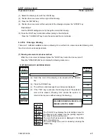
(4) Changing the display data (NOTE: Japanese draft has been reedited in this paragraph)


The display data can be changed to suit your needs. The following display items can be changed: 


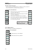
All marks and mark numbers can be turned ON or OFF, respectively. 


The waypoint data can be changed to lat/lon, date/time or comment/depth. 

Use the following procedure to do so. 


0093161022-06 

6-25 

Содержание MDP-621

Страница 1: ...MDP 621 MDP 641 MDP 640 MDP 600SER OM E 0093161022 07 ...

Страница 2: ...d by the notified body and is in conformity with the standards EN 60945 2002 Clauses 9 10 12 EN 62252 2004 Clauses 4 8 4 33 5 8 5 33 and Annex D ITU R Recommendation RM 1177 and complies with the essential requirements of Directive 1999 5 EC Conformity procedure under Annex IV of 1999 5 EC Technical Construction file has been undertaken by QinetiQ 0191 Fort Cumberland Road Eastney Portsmouth Engla...

Страница 3: ...e document only the document number of the relevant sheet s and cover sheet are modified and the rest of the sheets are not changed The document number is shown in the footer area right or left bottom of each sheet c 2004 2005 2006 2007 Koden Electronics Co Ltd All rights reserved No part of this publication may be reproduced transmitted translated in any form by any means without the written perm...

Страница 4: ...nside or on the equipment near operation lo cations to provide information about safety items and operation precautions Ensure that you clearly understand the meanings of each symbol and take necessary precau tions BEFORE using the equipment This indicates high voltages with a risk of serious electric shock if the part is touched NEVER touch the part with bare hands etc This symbol prohibits the o...

Страница 5: ...come 100 W m2 0 8 m Distance at which RF power density level to become 10 W m2 8 m 2 There is a risk of receiving electric shock if these parts are touched by accident Only qualified personnel should remove covers on these parts 1 2 WARNING for Display Unit There is a risk of receiving electric shock if these parts are touched by accident Only qualified personnel should remove covers on these part...

Страница 6: ...the main power supply Notify your authorized Simrad dealer or technical service center as soon as possible The liquid crystal display as well as some of the internal components of this radar can be dam aged by dropping or excessive force due to impact Mount the unit so that it will not be subject to these forces Mercury Hg is used in the LCD backlight When the unit is taken out of service it shoul...

Страница 7: ...ot be retrieved once it is erased Additional Notice on Fish Finder Processor Unit CVB 20 1 Power Switch CVB 20 does not have an independent power switch Power is always on while it is plugged to the power source CVB 20 s power is not off even if the main display unit is off We recommend to using the switch on the distributor or connecting with a separate switch to put the power off when the CVB 20...

Страница 8: ...t Composition Chapter 3 Specification Chapter 4 Installation Chapter 5 Basic Operation Chapter 6 Plotter Operation Chapter 7 Radar Operation Chapter 8 Sounder Operation Chapter 9 Navigation Data Operation Chapter 10 MENU Operation Chapter 11 Trouble Shooting Chapter 12 Maintenance 93161022 03 Main Index ...

Страница 9: ...ipment composition 1 1 1 3 1 Model outline 1 2 1 3 1 1 Radar Plotter 1 2 1 3 2 Network outline 1 3 1 3 2 1 Radar Plotter and Sounder 1 3 1 3 2 2 Radar Plotter multi display 1 4 1 3 2 3 Radar Plotter multi display and Sounder 1 5 1 4 Applied software 1 5 1 5 About GPS 1 6 1 6 About radar 1 7 1 6 1 What is radar 1 7 1 6 2 Characteristics of Radar Wave 1 7 93161022 03 Contents ...

Страница 10: ...map overlaid radar screen as multimode screens on a single screen or split screen The device has worldwide C Map NT MAX charts as its standard For creating original charts the desired C Map USER C CARD shall be provided by the purchaser 1 2Applicable technical standard The Radar Plotter meets with the requirements of IEC 60945 Edition 3 general requirements for marine electronic equipment 1 3 Equi...

Страница 11: ...A B Type GPS Sensor Option Transceiver RB716A 4kW Open Aerial 3 ft RW701A 03 4 ft RW701A 04 NMEA 0183 I O Option To Network Option Transceiver RB714A 2kW Radome 1 2 ft Transceiver RB715A 4kW Radome 2 ft GPS Compass Option KGC 1 7 inch Display RGD 600 Figure 1 1 Outline of Radar Plotter models 1 2 0093161022 06 ...

Страница 12: ...ne 1 3 2 1 Radar Plotter and Sounder GPS 20A B Type GPS Sensor Option Transceiver Open Transceiver Radome GPS Compass Option KGC 1 NMEA 0183 I O RGD 600 Or RGD 120 Sounder unit CVB 20 Transducer Option Option Figure 1 2 Network outline of Radar Plotter and Sounder 0093161022 06 1 3 ...

Страница 13: ...otter multi display GPS 20A B Type GPS Sensor Option Transceiver Open Transceiver Radome GPS Compass Option KGC 1 NMEA 0183 I O Option Option 1st Display RGD 600 Or RGD 120 2nd Display RGD 600 Or RGD 120 Figure 1 3 Network outline of Radar Plotter multi display 1 4 0093161022 06 ...

Страница 14: ...on KGC 1 NMEA 0183 I O 100 10BaseT HUB Sounder unit CVB 20 Transducer 1st Display RGD 600 Or RGD 120 Option Option 2nd Display RGD 600 Or RGD 120 3rd Display RGD 600 Or RGD 120 Figure 1 4 Network outline of Radar Plotter multi display and Sounder 1 4 Applied software Table 1 2 The software kits and types Device model Software kit Software type Radar Plotter KMC 103 Program ROM 0093161022 06 1 5 ...

Страница 15: ...eferenced to each satellite position The GPS receiver position Point of position fix is the point where 3 spheres intersect Figure 1 5 Constellation of GPS satellites NOTE The GPS system is based on the geodetic system called WGS 84 In conventional world maps one coordinate system differs from others with region and this causes the position fix made on the map and GPS measurement to differ in the ...

Страница 16: ...gned to allow the radio wave to be emitted in a fan shaped beam Due to this characteristic radar provides high definition picture in azimuth stable detection in elevation even if own ship rolls or pitches As an index of the antenna performance there are functional parameters called horizontal beam width and side lobe As shown in the following figure the side lobe is a residual transmission to each...

Страница 17: ...o catch Because there is not much to reflect a signal back to you a coastline can actually be closer to your boat than it appears on the screen Apparent coastline Actual invisible coastline Invisible Visible 3 1 Figure 1 8 Targets difficult to display on screen Shadow zones of radar Radar waves propagate in a straight line like light A high outcropping of land or a large ship will create a shadow ...

Страница 18: ...ost echo Direction of ghost echo 3 1 HU Figure 1 9 False echoes of radar Ghost echoes B Multiple echoes If there is a large vertical reflecting surface near your boat as in the case when you pass along side a large ship radar signals are repeatedly bounced back and forth between your boat and the other object Two to four images appear on the screen at equal intervals in the same bearing This is ca...

Страница 19: ...your boat than the radar s maximum distance range What appears onscreen is a false echo that looks to be nearer than the actual target Since the true echo from the distant target is outside the measurement capabilities of the radar its apparent distance will change when you change ranges and you can conclude that it s a false echo Radar interference If another boat s radar is operating on the same...

Страница 20: ...er 2 Operation manual Equipment Composition Chapter 2 Equipment Composition Page No 2 1 Standard equipment list 2 1 2 2 Spare parts list 2 2 2 3 Installation materials list 2 2 2 4 Option items list 2 3 93161022 03 Contents ...

Страница 21: ... 10m cable 10kg 4 Radar Antenna Selection 4kW Open RB716A Antenna Selection 3ft RW701A 03 4ft RW701A 04 With 10m cable 21kg RW701A 03 22kg RW701A 04 1 5 CW 380 5M To Other Unit 6 LANcable CW 385 5M To HUB 5m 1 7 DCPowercable CW 249 2M For Display 2m 1 8 Hood C23MB41102 1 9 Spare parts Refer to Spare parts lists 2 2 1 set 10 Installation materials Refer to Installation materials lists 2 3 1 set 11 ...

Страница 22: ...antenna motor 12VDC 5φx20mm 2 4 Carbon brush 24Z125209B Attached to antenna drive motor 1 set 2 3 Installation materials list 1 MDP 621 641 No Item name Description Remarks Q ty 1 Hexagonal bolt B10 25U For antenna unit mounting 4 2 Spring washer SW10U For antenna unit mounting 4 3 Plain washer 2W10U For antenna unit mounting 4 2 MDP 640 No Item name Description Remarks Q ty 1 Hexagonal bplt B12 5...

Страница 23: ...ads both ends For power supply 3m 11 CW 373 5M 6P watertight connector LTW on both ends 5m 12 CW 374 5M 6P watertight connector LTW one end 6P connector Nissin other end 5m 13 CW 375 5M 6P watertight connector LTW 6P watertight connector Conxall other end 5m 14 Connecting cable For Navigator unit CW 376 5M 6P watertight connector LTW one end Flying leads other end 5m 15 CW 380 2M 5P watertight con...

Страница 24: ... MRD99 FM KIT 24 Operation manual MDP 600SER OM E English 25 Final drawing MDP 621 FP MDP 641 FP MDP 640 FP English Japanese 26 Installation drawing MDP 621 ID MDP 641 ID MDP 640 ID English Japanese 27 Approval drawing MDP 621 AD MDP 621 AD MDP 640 AD English Japanese 28 Test data MDP 621 TD E MDP 641 TD E MDP 640 TD E English 2 4 0093161022 06 ...

Страница 25: ...Antenna specifications 3 2 3 2 3 Display specifications 3 2 3 2 4 ATA specifications 3 3 3 3 Plotter section 3 3 3 4 Sounder section 3 4 3 5 Power requirements 3 6 3 6 Environmental conditions 3 6 3 7 External dimensions and weight 3 7 3 7 1 Display 3 7 3 7 2 Radar antenna 3 7 3 7 2 1 RB714A 3 7 3 7 2 2 RB715A 3 8 3 7 2 3 RB716A 3 8 93161022 03 Contents ...

Страница 26: ...water temperature wind speed Input sentences accepted L L GGA GLL RMA RMC HEAD HDT HDG VHW HDM HCC VTG SPEED VHW VTG RMA RMC DEPTH DBT DPT MAG VAR RMA RMC HDG HVD HVM TEMP MTW NOTE Arrows indicate priority order Furthest left sentence has the highest and the furthest right sentence the lowest priorities respectively b Outputs Own ship s position ship s speed ship s course course deviation water de...

Страница 27: ... Peak power output RB714A 2kW RB715A 716A 4 kW 3 Frequency RB714A 9445 30MHz RB715A 716A 9410 30 MHz 4 Beam width RB714A 6 0 o 25 o Horizontal Vertical RB715A 3 9 o 25 o RB716A 2 5 o 22 o RW701A 03 1 8 o 22 o RW701A 04 5 Turning rate RB714A 24 rpm RB715A 716A 24 48 rpm 6 Transmission pulse length RB714A 0 12us 0 3 us 0 8 us RB715A 716A 0 08us 0 25 us 0 8 us 7 IF center frequency 60 MHz 8 Operation...

Страница 28: ...ions Interference rejection zoom sleep mode picture hold mode parallel cursor stern marker pulse length switch L L cursor 3 2 4 ATA specifications NOTE Connection of the ATA board MRE 310 is required 1 Acquisition AUTO Manual 2 Tracking Automatic 3 Number of tracking targets Up to 10 targets 4 Numerical data output Distance bearing speed CPA TCPA 5 Alarm Collision alarm and lost alarm 6 On screen ...

Страница 29: ...kup ゚ Own ship s tracks marks routes other ship s track POB graphics Storage devices SRAM data retained by Lithium battery CR 2032 and non volatile ROM Read Only Memory 21 Data memory card ゙ Storage recall delete initialization 22 Alarm Arrival alarm POB alarm course deviation speed alarm 23 Display Compass fairway Nav data 24 Numeric position display latitude longitude Loran C LOP Decca LOP 25 Na...

Страница 30: ...mal Zoom Normal Bottom Discrimination Normal NOTE The A scope can be added to above presentation modes 9 Auto functions Range shift 10 Output setting Standard low 11 Interference reduction Off low high 12 Image speed 4 1 2 1 1 1 1 2 1 4 1 8 1 16 1 32 and stop 13 Color rejection 15 steps one out of 15 colors 14 Color tone 3 steps 1 2 3 15 Background color 10 steps 0 1 2 3 4 5 6 7 8 9 16 Image mix t...

Страница 31: ...ower Consumption 55W or less MDP 621 60W or less MDP 641 70W or less MDP 640 2 AC operation The AC DC rectifier PS 010 is required Input voltage range 100 115 VAC or 200 230 VAC Permissible input voltage variation 10 Permissible input voltage frequency variation 47 63 Hz 3 6 Environmental conditions 1 Temperature Display 15 to 55 Antenna 25 to 55 2 Humidity 93 or less at 40o C 3 Vibration Display ...

Страница 32: ...tions 3 7 External dimensions and weight 3 7 1 Display Dimensions 247 H x 220 W x 133 5 D unit in mm Weight 3 5 kg 247 220 133 5 220 3 7 2 Radar antenna 3 7 2 1 RB714A Dimensions 220 H x 448 W x 448 D unit min Weight 6 Kg Bow 448 448 220 0093161022 07 3 7 ...

Страница 33: ...36 W x 636 D unit in mm Weight 10 Kg 636 660 636 255 Bow 3 7 2 3 RB716A Dimensions 450 H x 1034 W x 390 D RW701A 03 unit in 0mm Dimensions 450 H x 1346 W x 390 D RW701A 04 unit in mm Weight 21kg RW701A 03 22kg RW701A 04 1034 RW701A 03 1346 RW701A 04 450 220 390 234 280 104 Bow 3 8 0093161022 07 ...

Страница 34: ...e Scanner Unit 4 6 4 4 2 3 Installing the aerial 4 8 4 5 Cables connections 4 8 4 5 1 Connecting scanner unit 4 8 4 5 1 1 RB714A Radome scanner 4 8 4 5 1 2 RB715A Radome scanner 4 10 4 5 1 3 Interconnecting cable RB716A 4 12 4 5 1 4 Grounding wire 4 14 4 5 2 System connection 4 15 4 5 2 1 Connection of stand alone system 4 15 4 5 2 2 Connection of two device system 4 16 4 5 2 3 Connection of multi...

Страница 35: ...ection of each unit and the accessories Carefully check the exterior of each unit for dents damage etc Also check the inside of each unit in view of electrical and mechanical damages 4 4 The units setting To obtain best operational performance the following factors must be considered 4 4 1 Display unit installation The display unit is designed for table mount and flush mount Refer to the following...

Страница 36: ...n manual 80 3 1 8 168 6 5 8 Knurled fixing bolt Unit in mm inch Mounting bracket M5 screw 4 pcs Fixing screws Display Figure 4 1 Fitting detail of display 100 3 15 16 3 1 8 80 80 3 1 8 Figure 4 2 Service space required for display 4 2 0093161022 06 ...

Страница 37: ...ce 4 Put the display on the opening and fix with four 4 tapping screws In case you use M4 screws to fix the display select an appropriate screw length that best suits fixing the unit to the panel thickness 5 Refit the coverings removed in step 3 NOTE FLUSH MOUNT KIT COM7 MRD99 FM KIT is extra cost option E45MB11090 Packing Fixing holes for M4 screw 4 pcs Screw covers 4 pcs Fixing screws M4 screws ...

Страница 38: ...stacle place the scanner on the bow side of it When installing the scanner on a mast position it in front of the mast If obstacles cannot be avoided for structural reasons refer to Shifting away from obstacles in Section 4 4 2 1 4 Do not install the scanner near hot or heat generating items Do not install the scanner where it may be subjected to smoke or hot air from exhausts or heat from lights 5...

Страница 39: ...n keel line R distance from scanner to obstacle Ls 0 4R D 2 m when R 15m Ls 0 025R D 2 m when R 15m Where Ls distance to be shifted from keel line D diameter of obstacle on keel line R distance from scanner to obstacle Obstacle D Ls R Scanner Unit Keel line Figure 4 4 Shifting from keel line 2 Obtaining sufficient dip angle Raise the scanner position so that there is a sufficient dip angle θ avail...

Страница 40: ...with this manual to drill five holes for mounting the scanner Attach the four bolts and feed the drain tube through the fifth hole The bolts included with your unit will suffice for mount base thickness of 9 to 14 mm 0 35 to 0 55 in If the mount base is thicker or thinner refer to Table 4 4 2 Use a silicone sealant to prevent the bolts from working loose The housing may be damaged if you use a thr...

Страница 41: ... Bolts necessary to Fix radome scanner Material Remarks 1 4mm 0 04 0 16 in M10 15 1 5mm pitch Stainless 4 9mm 0 16 0 35 in M10 20 1 5mm pitch Stainless 9 14mm 0 35 0 55 in M10 25 1 5mm pitch Stainless Included with radar 14 19mm 0 55 0 75 in M10 30 1 5mm pitch Stainless Table 4 2 Bolts for Mounting Scanner Unit Open scanner Thickness of Mount base Bolts necessary to Fix radome scanner Material Rem...

Страница 42: ...re chase or conduit tape the scanner side connector to the wire so it doesn t pull off or get hung up Secure cables in place at intervals of about 40 cm 16 4 5 1 Connecting scanner unit 4 5 1 1 RB714A Radome scanner 1 Be sure that the power is off 2 Remove the upper part of the radome from the scanner unit Lift it vertically to avoid bumping it against the antenna There are four fixing screws Fixi...

Страница 43: ... cover 7 Replace the upper part of the radome being careful not to bump it against the antenna Make sure that the cover is positioned in the correct direction as shown in Fig 4 10 The upper and lower parts of the radome each have four alignment markings indicating screw positions Stern Aerial Shield cover Shielding braid Fixing plate Rubber seal Antenna cable Radome bottom Figure 4 10 Installing t...

Страница 44: ... ring and clamp the cable to the scanner unit with screws on the fixing plate Attach the 7 pin connector to X11 and 9 pin connector to X12 of the printed circuit board 6 Replace the aluminum cover Lay the cable shield into the channel machined into the aluminum housing Be careful that the cable will not get caught up between the main unit and cover 7 Replace the upper part of the radome being care...

Страница 45: ...ix connector on PCB X11 X12 Antenna Stern side Shield cover Cable shield Radome bottom Fixing plate Rubber ring Interconnecting cable X12 Connect here PCB Inner shield X11 Connect here Radome bottom Figure 4 12 Fitting interconnecting cable 0093161022 06 4 11 ...

Страница 46: ...fixing plate rubber seal and washer that secure the cable Pass the cable through as shown in the diagram below replace the above items and tighten the bolts 7 Return the transceiver to its original position and secure it with the bolts you removed 8 Connect the 7 pin connector to X11 and the 9 pin connector to X12 of the printed circuit board and connect the two connectors that you removed in Step...

Страница 47: ...k tube remove any of it MAX 5 mm Fixing bolt Cable shielding terminal Washer Fixing plate Scanner unit Inter connection cable Sealing rubber Cable inlet Heading switch connector X2 Motor connector X1 Inter connection cable This part enlarged Clamp Fixing bolt Fixing plate TR unit fixing bolts Figure 4 13 Fitting interconnecting cable 0093161022 06 4 13 ...

Страница 48: ...t Connect a grounding wire from one of the bolts on the scanner base as shown in Figure 4 13 The crimp terminal and grounding wire are customer supplied items WARNING Figure 4 14 Grounding for Radome scanner unit Radome bottom Platform Chassis To ship s hull Crimp terminal Grounding wire Grounding wire Scanner cover To ship s hull Figure 4 15 Grounding for Open scanner unit 4 14 0093161022 06 ...

Страница 49: ...e with connector standard for MDP series Connecting cable customer supply Connector type LTWBD 08BFFA L180 option Earthing lead RB714A RB715A 10 8 31 2VDC CW 249 NMEA 0183 input 5m cable w th i connector These items are optional all connected to NMEA ports at the display rear panel Connector type LTWBD 06BFFA L180 Connecting cable Customer supply CW 374 CW 373 CW 375 CW 376 NMEA 0183 RB716A Figure...

Страница 50: ...1 To external buzzer Connecting cable customer supply Connector type LTWBD 08BFFA L180 option Earthing lead See para 4 5 2 1 Antenna cable 10m cable with connector standard MNEA 0183 input RB714A RB715A CW 249 CW 380 5M 5m cable with connector NMEA 0183 input See para 4 5 2 1 RB716A or or Sounder unit CVB 20 7 inch Display RGD 600 10 4 inch Display RGD 120 Figure 4 17 Two device system Connections...

Страница 51: ...uzzer Connecting cable customer supply Connector type LTWBD 08BFFA L180 option Earthing lead See para 4 5 2 1 Antenna cable 10m cable with connector standard MNEA 0183 input RB714A RB715A CW 249 CW 385 5M To 10BaseT HUB customer supply 5m cable w th i connector NMEA 0183 input See para 4 5 2 1 WARNING Buy the hub for the MDP series and connect only the MDP series RB716A Figure 4 18 multi device sy...

Страница 52: ...y connection If you don not connect your radar to external equipment tape the ends of the red and green wires Be certain to locate the fuse where it will be kept dry And then plug the power supply cable into the connector labeled POWER on the rear panel of the display unit When extending the power supply cable size the wire as follows Boat Power Voltage Cable conductor Cable max Length Cross secti...

Страница 53: ... 2 TX 3 GND 4 RX 5 RX 6 NC 1 GND 2 GPSOUT 3 GND 4 GPSIN 5 GPSIN 6 12V 1 RXD 2 TXD 3 BUZ1 4 BUZ2 5 12V 6 GND 7 5V 8 GND 1 LPTX 2 LPTX 3 LPRX 4 LPRX 5 GND 1 250V 2 24V 3 12V 4 GND 5 DAT R 6 DAT 7 NC 8 BP SHF 9 BP SHF R 10 V TRIG 11 NC 12 MOTOR 13 MOTOR 14 V TRIG R 15 MOTOR 16 MOTOR 1 5 2 3 4 1 5 6 2 3 4 1 5 6 2 3 4 8 16 15 13 12 11 9 8 7 2 3 4 6 1 5 10 14 7 1 5 2 3 4 1 5 6 2 3 4 0093161022 06 4 19 ...

Страница 54: ... See section 10 2 9 3 4 Chart Source Setting See section 10 2 9 4 5 Sounder Source Setting See section 10 2 9 5 6 Subnet Mask Setting See section 10 2 9 6 7 Gateway Address Setting See section 10 2 9 7 8 Offset Port Number Setting See section 10 2 9 8 WARNING When a radar antenna is connected be sure to perform the following adjustments and set ups before operating the system Otherwise the radar p...

Страница 55: ...5 5 5 4 2 Selecting the display screen 5 8 5 4 3 Changing the registration screen 5 9 5 5 Setting up display colors and adjusting screen display brightness panel illumination 5 12 5 5 1 Adjusting the screen display brightness 5 12 5 5 2 Adjusting the panel illumination 5 13 5 5 3 Setting up the display colors 5 13 5 6 Changing the operating screen via the FUNC key 5 14 5 7 Operating the cursor ON ...

Страница 56: ...rforms all operations of Radar Plotter Sounder NAV etc POWER Power supply on off radar transmit standby POB Stores present location in an emergency Selects range scale BRILL Sets up screen display colors day and night and adjusts screen brightness and panel illumination MENU Displays the menu screen DISP Selects screen display key POB key SOFT key FUNC key Rotary control BRILL key MENU key CURS ke...

Страница 57: ...on the power supply Rotary control Used for adjusting the GAIN STC VRM EBL etc and selecting the display mode menu etc GOTO CURS Displays the destination and route soft menu 1 Performs soft menu operations Turns on off the cross cursor when operating the Plotter 6 to FUNC Changes the operating screen display Used for moving the cross cursor and map as well as menu selection ...

Страница 58: ...t 3 seconds before turning the power supply back on after turning off and vise versa If the screen display appears odd turn the power supply off and on again Model name ROM version A system self test for memory and battery voltage is automatically carried out A buzzer sounds and OK is displayed if system passes or NG is displayed if system fails For battery replacement consult the nearest KODEN de...

Страница 59: ...e functions displayed by pressing the associated keys of the soft menu The soft menu automatically disappears 30 seconds after the completion of the operation Example of soft key menu display during Plotter operation MARK MARK TRACK TRACK ERASE P FUNC NEXT The current specific operating system is displayed In this example PLOTTER is the current operating system RADAR SOUNDER NAV are also available...

Страница 60: ...ore we suggest you create a variety of personalized screens to suit your specific needs 5 4 1 Types of display screen There are 2 types of screen display combinations shown below The image displays that can be used on each screen are listed below In each screen display combination the navigation data NAV is displayed at the top of the display area 1 1 Navigation data 1 2 1 2 PLOTTER SOUNDER RADAR ...

Страница 61: ... displayed instead of COG WAYPOINT BRG RNG 34 34 5670 134 23 4560 N E 359 3 25 6nm POSITION COG SOG 34 23 4560 134 24 1230 N E 335 3 15 3kt WIND DIR WIND SPEED TEMP DEPTH ETA TTG TIM XXX X 12 3 kt 17 6 256 7 m 12 25 14 10 09 08 05 02 Waypoint position Waypoint bearing Waypoint range Wind Direction Wind Speed Water temperature Water depth Own position Course over ground Ship s speed Estimated time ...

Страница 62: ... set by using the XTE AREA soft menu in Navigation Data operation in Chapter 9 If the waypoint is located far outer than 4 nm sm or km the course length shown on the screen is set to 4 nm sm or km Every 2 nm sm or km of the ship s advancement the ship s profile mark is reset to the original position providing a 4 nm sm or km forward range When the ship gets to the point less than 4 nm sm or km to ...

Страница 63: ...d The cursor will highlight the icon s border 3 Press soft key 6 ENTER The screen designated by the cursor is displayed Note If the procedure stops midway through operation screen does not change press the DISP key once more The system will return to the previous screen SELECT MODE DISP CREATE ENTER DISPLAY SELECT DISP SELECT is displayed to indicate screen selection mode SELECT MODE DISP CREATE E...

Страница 64: ...screen selection mode appears 2 Using the rotary control position the cursor over the icon of the registration screen to be changed The icon created for the new screen display is registered at the cursor location MODE DISP CREATE ENTER DISPLAY SELECT DISP SELECT is displayed to indicate screen selection mode MODE DISP CREATE ENTER DISPLAY SELECT Rotary control Cursor CREATE ...

Страница 65: ...s the designated screen image to 1 2 of the screen Bottom This icon registers the designated screen image to 1 2 of the screen Top This icon registers the designated screen image to the entire screen DISP FULL ENTER 1 2 TOP 1 2 BOTTM RADAR PLOT SNDR OVRLY NAV NAV 3D OV 3D PL SD HIWAY CMPAS Registration screen change mode screen screen CREATE The screen created in the screen mode is displayed Initi...

Страница 66: ... operation stops when changing the registration screen press the DISP key The display screen returns to the previous screen The screen that was being changed during the operation is not registered and the system returns to the previous registration screen DISP FULL ENTER 1 2 TOP 1 2 BOTTM RADAR PLOT SNDR OVRLY NAV NAV 3D OV 3D PL SD HIWAY CMPAS screen CREATE The icon is now displayed with Plotter ...

Страница 67: ...ANEL COLOR is displayed 3 Press soft key 6 RETURN or the BRILL key to complete the BRILL adjustment setup soft menu 4 Furthermore the soft menu will automatically close if no keys are pressed for more than 30 seconds 5 5 1 Adjusting the screen display brightness 1 Press soft key 1 SCREEN A screen display brightness adjustment box is displayed lower left corner 2 Using the rotary control adjust the...

Страница 68: ...layed lower left corner 2 Change the settings using the pointing keypad or the rotary control The item highlighted by the cursor bar is set The display color settings for the Plotter have been set The display colors settings for the Radar can be changed in the Radar preset menu PANEL 50 Moving the rotary control in a clockwise direction will increase the illumination Moving the rotary control in a...

Страница 69: ...he FUNC key is used to change the operating screen in the order shown in the diagram below However the screens that are not involved in the operation Compass Highway NAVDATA are not selected As an example we will explain how to change the screen to a Radar Plotter split screen 38 05 620 138 27 311 15 3 359 5 SOG COG N E PLOTTER MARK MARK ERASE TRACK TRACK ERASE P FUNC NEXT Navigation data Radar Pl...

Страница 70: ...thermore each screen will have the following Plotter screen The POB location becomes a WP NAV DATA screen The WP changes into POB data HIGHWAY COMPASS screen The WP changes into POB data Navigation Data screen The background color changes from gray to red Updating the POB position and canceling the audio alarm 1 Press the POB key again The next soft menu will be displayed 2 If the POB is canceled ...

Страница 71: ... cursor moves in the direction the pointing keypad RETURN ALM CLEAR POB UPDATE POB CANCEL 1 2 3 4 5 6 Cancel the audio alarm The POB operation continues The POB position is updated to current position Cancels the POB registration 38 05 620 138 27 311 15 3 359 5 38 05 620 138 27 311 15 3 359 5 If the pointing keypad is moved in the right the cursor mark moves to the right If the pointing keypad is ...

Страница 72: ...or removing the C MAP card the cover shown in the diagram below opens and closes The cover opens in the direction of the arrow Make sure you close the cover all the way until you hear it click into place Push cover tab slightly to the lower Cover opens in the direction of the arrow Insert remove card Close cover 1 2 3 4 6 POB POWER 1 2 ...

Страница 73: ...ecting the ship s track color and erasing 6 11 6 4 5 Changing the screen display mode 6 12 6 4 6 Moving to the center of the screen 6 13 6 4 7 Off center 6 13 6 4 8 Fixed scale function 6 14 6 4 9 Viewing the map information 6 15 6 4 10 Drawing 6 16 6 4 10 1 Inputting a drawing 6 16 6 4 10 2 Erasing a drawing 6 17 6 4 10 3 Editing a drawing 6 18 6 4 11 Auto scale 6 20 6 5 Setting the waypoint rout...

Страница 74: ... 27 311 Ship s path Number of points on the track Figure 6 1 Plotter screen Note To read the map of a new place from the C MAP card by using the network it will be displayed after a few seconds 6 2 Changing the scale of the screen The scale of the screen can be changed by carrying out the following procedure If the range up key is pressed the screen is zoomed out If the range down key is pressed t...

Страница 75: ... position mark is displayed inside the screen Use this feature if you want to view a large area around own ship Note Operation cannot be performed when own ship s mark is not inside the screen area Figure 6 2 Moving the screen with the pointing keypad In the diagram above the area towards the right of the screen moves more into view when the pointing keypad is moved to the right Do this operation ...

Страница 76: ... 5 6 TRACK COLOR RETURN 2 ON OFF 1 2 3 4 5 6 ERASE COLOR RETURN 1 AREA START AREA END 1 2 3 4 5 6 FUNC PLOTTER MARK MARK ERASE TRACK TRACK ERASE P FUNC NEXT PLOTTER PAGE1 PLOTTER D MODE 5 CENTER OFF C FX SCL P FUNC PREV 1 2 3 4 5 6 FUNC PLOTTER PAGE2 NEXT PREV RETURN 6 1 2 3 4 5 MOVE INSERT 1 2 3 4 5 6 INFO PREV NEXT RETURN PAGE PAGE 1 2 3 4 5 6 INFO DRAW RETURN CREATE DRAW ERASE DRAW EDIT A SCL O...

Страница 77: ...KIP CURSOR 1 2 3 4 5 6 ENTER M NO COLOR RETURN ON OFF 1 SHAPE 3 CMNT ON OFF 1 2 3 4 5 6 SYMBOL M NO RETURN ON OFF ON OFF D DATA CHG 1 2 3 4 5 6 COLOR RETURN SHAPE 4 SELECT 2 1 2 3 4 5 6 GOTO SERRCH RETURN SET D DISP EDIT DELETE WP NAV 1 2 3 4 5 6 CMNT WPT EDIT RETURN LIST DELETE WPT WPT EDIT INSERT WPT 1 2 3 4 5 6 GOTO SAVE EDIT RETURN DELETE CHG D DATA RT NAV See section 6 5 During waypoint or ro...

Страница 78: ... group NEXT Displays page 2 of top group TRACK Sets up ship s track MARK ERASE Erases mark MARK Input mark Corresponding to soft keys 1 to 6 with graphics PLOTTER MARK MARK ERASE TRACK TRACK ERASE P FUNC NEXT PLOTTER PAGE1 Soft menu Directory display If the GOTO key is pressed the destination route navigation soft menu will be displayed See page 6 21 If soft key from 1 to 6 and the FUNC key is pre...

Страница 79: ... RED YEL DBL BLU PNK WHT COLOR selects the mark color If the key is pressed the settings menu will be displayed Carry out the settings using the pointing keypad or rotary control The mark color that has been setup is displayed in the soft menu If the ENTER key is pressed the mark is registered with the color and shape that was setup in COLOR and SHAPE When the cross cursor is on cross cursor posit...

Страница 80: ... PLOTTER PAGE1 and press the MARK ERASE key The detailed mark erase menu is displayed PLOTTER PAGE1 MARK ERASE ASSIGNED ONE MARK MORE THAN TWO MARKS WILL BE ERASED ARE YOU SURE ERASE RETURN PLOTTER PAGE1 SHAPE COLOR YES NO 1 Position the cursor on the mark to be erased Press the 2 ERASE key e shown below 4 y is pressed the mark will be uses the system to return to the top 3 The soft menu and messa...

Страница 81: ...lor The mark color that has been set is displayed in the soft menu If ALL is selected all colors will be selected for erasure 7 ALL PLOTTER PAGE1 MARK ERASE YES NO PLOTTER PAGE1 1 Select the color and shape of the mark to be erased 2 Press the ERASE key 3 The soft menu and message shown below are displayed 4 If the YES key is pressed the mark will be erased NO causes the system to return to the to...

Страница 82: ...GRN RED YEL DBL BLU PNK WHT COLOR TRACK ON TRACK OFF RETURN Every time TRACK is pressed the track is switched ON and OFF ON Ship s track is displayed Store a ship s track OFF Ship s track is not displayed Not store a ship s track COLOR selects the color of the ship s track This key displays the color settings menu Use the pointing keypad or the rotary control to set the color The color that has be...

Страница 83: ...isplay the soft menu PLOTTER PAGE1 and press the TRACK ERASE key The ship s track erase menu is displayed 1 Position the cross cursor at the start of the area to be erased and press the AREA START key 2 Position the cross cursor at the end of the area to be erased and press the AREA END key 3 The soft menu and message shown below are displayed 4 If the YES key is pressed the ship s track in the as...

Страница 84: ...low are displayed 4 If the YES key is pressed the ship s track will be erased NO causes the system to return to the top menu without erasing the ship s track ASSIGNED TRACK LINE WILL BE ERASED ARE YOU SURE PLOTTER PAGE1 NO YES AREA END COLOR AREA START PLOTTER PAGE1 RETURN ERASE COLOR PNK BLU DBL YEL RED GRN 6 WHT ALL 7 5 4 3 2 1 0 COLOR selects the color of the ship s track to be erased If this k...

Страница 85: ...d in the area settings of the SYSTEM MENU Display the soft menu PLOTTER PAGE2 Every time the D MODE key is pressed the display mode is changed PLOTTER PAGE2 D MODE N UP R D MODE C UP T D MODE C UP R D MODE H UP Every time the D MODE key is pressed the display mode changes from N UP T S UP T N UP R S UP R C UP T C UP R H UP N UP T S UP T Note N UP can be changed to S UP in the zone settings of the ...

Страница 86: ... CENTER key is pressed own ship s position is moved to the center of the screen When the cross cursor is on If the CENTER key is pressed the cross cursor s position is moved to the center of the screen 6 4 7 Off center If you want to move own ship s position to an optional position on the screen cross cursor s position use the soft menu s OFF C function Display the soft menu PLOTTER PAGE2 PREV P F...

Страница 87: ...center position becomes the position of the cursor When the cross cursor is off the zoom in zoom out center position becomes own ship s position Display the soft menu PLOTTER PAGE2 PLOTTER PAGE2 D MODE N UP T PLOTTER PREV P FUNC FX SCL XX OFF C CENTER FX SCL YY FX SCL ZZ FX SCL XX Every time the FX SCL key is pressed the scale changes from XX YY ZZ XX The scale settings are set with the PLOTTER ME...

Страница 88: ...t menu PLOTTER PAGE1 2 P FUNC PLOTTER PAGE1 2 P FUNC NEXT PAGE RETURN PREV PAGE INFO PLOTTER PAGE1 DRAW EDIT RETURN A SCL OFF DRAW ERASE DRAW CREATE INFO PLOTTER PAGE1 If INFO is set to ON the map information is displayed on the screen The soft menu changes to next page NOTE A soft key to NEXT PAGE and PREV PAGE can be used when there are two or more pages of detailed information Shows previous De...

Страница 89: ... COLOR PLOTTER PAGE1 CLOSE END END ENTER XXX RETURN If the ENTER key is pressed the current position of the cross cursor is assigned as the drawing s location The XXX indicates the number of possible map to be entered Terminates the drawing creation Joins the start point and end point of the drawing and closes the drawing creation soft menu COLOR WHT PNK BLU DBL YEL RED GRN 6 5 4 3 2 1 0 The COLOR...

Страница 90: ...ss the CURS key to turn the cross cursor off Press the DRAW ERASE key to display the drawing erase menu PLOTTER PAGE1 2 P FUNC DRAW ERASE PLOTTER PAGE1 COLOR AREA START RETURN AREA END ERASE PLOTTER PAGE1 YES NO COLOR DBL YEL RED 4 5 BLU PNK 6 WHT 7 ALL 3 2 1 0 GRN a Select the color of the drawing to be erased with the COLOR key b Press the ERASE key c The soft menu and message shown below are di...

Страница 91: ...nd press the AREA START key b Position the cross cursor at the end of the area to be erased and press the AREA END key c The soft menu and message shown below are displayed d If the YES key is pressed the drawing in the assigned area will be erased NO causes the system to return to the top menu without erasing the drawing ASSIGNED DRAWING LINE WILL BE ERASED ARE YOU SURE 6 4 10 3 Editing a drawing...

Страница 92: ...s the system to return to the top menu without moving the node PLOTTER PAGE1 ENTER CANCEL ASSIGN NEW NODE POSITION BY CURSOR ASSIGN NODE POSITION BY CURSOR 2 Inserting a drawing node Press the INSERT key The drawing node insert menu and message are displayed ASSIGN LINE POSITION BY CURSOR a Position the cross cursor on the line where you want to insert the node b Press the ENTER key c The message ...

Страница 93: ...s on the screen display Display the soft menu PLOTTER PAGE1 2 P FUNC PLOTTER PAGE1 2 P FUNC PLOTTER PAGE1 DRAW EDIT RETURN A SCL OFF DRAW ERASE DRAW CREATE INFO A SCL ON If A SCL is set to ON the AUTO SCALE function activates If A SCL is set to OFF the AUTO SCALE function is turned off 9 スケール表示 DGPS NU T 0003 N 135 o 27 611E 210 o 2 3nm 35 o 05 123N Destination is displayed on the screen at all ti...

Страница 94: ...PLOTTER PAGE1 GOTO CURSOR CLEAR SKIP 1 Move the cross cursor to the destination Or the first point to steer to 2 Press the GOTO CURSOR key 3 The waypoint navigation starts towards the waypoint designated by the cross cursor 4 The soft menu shown below is displayed DELETE SAVE PLOTTER PAGE1 ADD CURSOR RETURN The entered waypoint or route position data is registered The year month day hour minute an...

Страница 95: ...0 000N 135 90 000E 0008 35 80 000N 135 80 000E 0007 35 70 000N 135 70 000E 0006 0005 0004 35 40 000N 135 40 000E 0003 35 30 000N 135 30 000E 0002 35 20 000N 135 20 000E 0001 35 10 000N 135 10 000E 0000 35 00 000N 135 00 000E WPT LIST Move the line cursor by press the up down key 1 key moves cursor down by one To display the next page Press the down key until line cursor exits from the bottom last ...

Страница 96: ...estination data can be easily loaded Press the SEARCH key to display the search menu Setup the mark number mark color mark shape and comment and then search the list GOTO WPT SEARCH RETURN ENTER PLOTTER PAGE1 COLOR ALL M NO OFF SHAPE ALL The list is searched using the assigned parameters The search results are displayed in the WPT LIST Mark Number Comment Mark Color Mark Shape CMNT OFF 20 100 8300...

Страница 97: ...Change the figure with the rotary control 4 Enter the number with the rotary control 5 When completed press the ENTER key to finish the settings left right cursor key 3 Place the cursor on to the next point to be changed with the 2 Enter the number with the rotary control 1 Place the cursor on to the point to be changed with the left right cursor key b Setting the mark color Press the COLOR key to...

Страница 98: ... 8 9 A B C D E F G H I J S _ T R Q P Z O Y L M N V W X K U COMMENT INPUT Move the cursor with the left right cursor key Change an alpha numeric figure with the rotary control 4 Enter the number with the rotary control 5 When completed press the ENTER key to finish the settings 3 Place the cursor on to the next point to be changed with the left right cursor key 1 Place the cursor on to the point to...

Страница 99: ...he mark display Applies to all registered data in the LIST irrespective of the cursor Every time the SYMBOL key is pressed all marks shown on the screen can be turned on or off If non display OFF is set the mark of the WPT LIST is displayed shaded in b Changing the mark number display Applies to all registered data in the LIST irrespective of cursor Every time the M NO key is pressed all mark numb...

Страница 100: ... 1 LAT 2 LON 3 DEPTH 4 DISP 5 M NO ON OFF ON OFF N E 0005 2003 12 25 08 23 35 1 When entering new data 1 The line cursor moves from 0 to 5 the following are set as a default DATE Current data time LAT LON 0 00 000 N 0 00 000 E DISP M NO ON a Setting the mark color COLOR WHT PNK BLU DBL YEL RED GRN 6 5 4 3 2 1 0 If the COLOR key is pressed the settings menu for the mark color will be displayed Use ...

Страница 101: ...003 06 19 06 17 25 ABCDEFGHIJKL WPT EDIT M NO DATE MARK 0 COMMNET 1 LAT 2 LON 3 DEPTH 4 DISP 5 M NO 35 10 000N 135 10 000E 980 ft ON OFF ON OFF 0001 2003 06 19 06 17 25 ABCDEFGHIJKL WPT EDIT M NO DATE MARK 0 COMMNET 1 LAT 2 LON 3 DEPTH 4 DISP 5 M NO 0001 2003 06 19 06 17 25 ABCDEFGHIJKL 35 10 000N 135 10 000E 980 ft ON OFF ON OFF Block cursor WPT EDIT M NO DATE MARK 0 COMMNET 1 LAT 2 LON 3 DEPTH 4...

Страница 102: ...he year month day hour minute and second information is automatically registered Changes the contents of the data displayed Edits the data selected by the line cursor Deletes the registered data 01 10 ABCDEFGHIJKL COMMENT PT R NO 10 09 08 07 06 05 04 06 GOOD POINT 03 12 BIG FISH 02 05 MNOPQRSTU ROUTE LIST Move the line cursor by press the up down key 1 key moves cursor down by one To display the n...

Страница 103: ...orward direction Backward direction When either forward direction or backward direction is selected the data selected by the line cursor is set as the route 2 Deleting the registered data a Move the line cursor over the data to be deleted b Press the DELETE key c The soft menu turns as shown on the right d By pressing the YES key the data selected by the line cursor is deleted The NO key brings th...

Страница 104: ...yet registered number Move the line cursor to the data to be edited or the number for the new entry and press the EDIT key The following soft menu and edit list are displayed GOTO ROUTE EDIT DELETE WPT INSERT WPT WPT LIST CMNT EDIT EDIT WPT RETURN PLOTTER PAGE1 ROUTE EDIT R NO PT COMMENT 01 01 ABCDEFGHIJKL P NO LAT LON 00 35 00 000N 135 00 000E 01 36 00 000N 136 00 000E 02 Edits the comment Displa...

Страница 105: ...the current position is set as the new origin 6 5 5 Canceling the waypoint and route navigation Press the GOTO key to display the soft menu PLOTTER GOTO The soft GOTO menu is displayed 1 If the CLEAR key is pressed the soft menu and message shown below are displayed 2 If the YES key is pressed the destination route navigation will be cancelled and the screen returns to GOTO display Pressing NO cau...

Страница 106: ...xt latest waypoint Can only be reset when conducting destination and route navigation Press the GOTO key to display the soft menu PLOTTER GOTO The soft GOTO menu is displayed RE START SKIP CLEAR PLOTTER PAGE1 ROUTE WPT Press the SKIP key The waypoint that the ship is currently heading for changes its direction to the next waypoint 0093161022 06 6 33 ...

Страница 107: ...ween 2 points FLOAT 7 11 7 4 7 Turning the fixed distance marker ON OFF RR 7 11 7 4 8 Deleting the ship s heading line 7 12 7 4 9 Target enhance ST 7 12 7 4 10 Changing the pulse length PULSE 7 13 7 4 11 Displaying the ship s trail TRAIL 7 13 7 4 12 Enlarging the screen image ZOOM 7 14 7 4 13 OFF CENTER OFF C 7 15 7 4 14 Alarm GZ 7 16 7 4 15 Setting up the power save function SLEEP 7 17 7 4 16 ON ...

Страница 108: ...lay Range Fixed marker interval Display mode GZ Alarm VRM1 EBL1 Target enhance Zoom Off center Trail EBL1 value VRM1 value EBL2 value VRM2 value VRM2 EBL2 Fixed marker Tuning meter ATA data display area Cross cursor Pulse length Cross cursor position data 135 o 27 611E 35 o 05 123N Navigation data display area 38 05 620 138 27 311 15 3 359 5 SOG COG N E Kt 24nm 6 0 HU L GZ IN A 123 5o 21 3nm 2 2 2...

Страница 109: ...s displayed 2 Press the STBY key to transmit The STBY turns to TX ON and the radar starts to transmit with the radar antenna rotated 3 To set the radar to standby press the TX ON key The TX ON changes to STBY and the radar is brought to standby In this state the radar can be quickly operated as soon as the STBY key is pressed 4 To turn off the soft menu press the RETURN key NOTE The soft menu auto...

Страница 110: ...play Range Speed Unit in the SYSTEM MENU Default setting is nm Fixed range marker intervals and marker numbers Initial range setting for nm for sm km Range Marker interval Marker number Range Marker interval Marker number 0 125 0 0625 2 0 25 0 125 2 0 25 0 125 2 0 5 0 25 2 0 5 0 25 2 0 75 0 25 3 0 75 0 25 3 1 0 0 25 4 1 0 0 25 4 1 5 0 5 3 1 5 0 5 3 2 0 0 5 4 2 0 0 5 4 3 0 1 0 3 3 0 1 0 3 4 0 1 0 4...

Страница 111: ... AT XX STC AT XX FTC AT XX R FUNC NEXT RADAR PAGE1 RADAR EBL1 OFF XX VRM1 OFF XX MODE 2 IR OFF 1 2 R FUNC PREV 1 2 3 4 5 6 FUNC RADAR PAGE2 NEXT PREV 1 2 3 4 5 6 AUTO MANUAL TUNE AT XX RETURN 1 2 3 4 5 6 EBL2 OFF XX VRM2 OFF XX FLOAT OFF ON RETURN RR OFF ON HL OFF 1 2 3 4 5 6 ST OFF 1 2 PULSE L S TRAIL 3 RETURN ZOOM OFF ON OFF C OFF ON 1 2 3 4 5 6 GZ V RNG RETURN SLEEP 4 TARGET 1 2 3 4 5 6 GZ STAR...

Страница 112: ...ely 30 seconds after finishing the operation After disappearing if the soft menu is displayed again the displayed menu will be the previous soft menu Corresponding to soft keys 1 to 6 AUTO Sets up automatic GAIN STC FTC GAIN STC FTC Adjusts sensitivity STC and FTC R FUNC Displays the Radar function group NEXT Displays page 2 of the top group RADAR AUTO AT1 GAIN AT STC AT FTC AT R FUNC NEXT RADAR P...

Страница 113: ...When the AUTO key is pressed AT1 AT2 HBR and OFF are changed sequentially NOTE When AUTO OFF is selected the GAIN STC and FTC controls are available in manual mode AUTO HBR RADAR PAGE1 GAIN AT FTC AT R FUNC NEXT RADAR STC AT AUTO AT1 AUTO AT2 Every time the AUTO key is pressed the function changes from AT1 AT2 HBR OFF AT1 AUTO OFF AT1 Use this function in harbors narrow or congested waterways and ...

Страница 114: ...ber Moving the rotary control to the right will increase the GAIN value while moving to the left decreases the value b Adjusting the STC If the STC key is pressed the STC adjustment box shown below is displayed The method of adjustment is the same as the GAIN adjustment c Adjusting the FTC If the FTC key is pressed the FTC adjustment box shown below is displayed The method of adjustment is the sam...

Страница 115: ...tment box is displayed Using the rotary control position the screen EBL1 cursor on the target and then read off the bearing To cancel EBL1 press the EBL1 key while the adjustment box is displayed 2 VRM1 Display the soft key menu RADAR PAGE2 and press the VRM1 key The VRM1 adjustment box is displayed Using the rotary control position the VRM1 marker on the target and read off the distance To cancel...

Страница 116: ...ings of the SYSTEM MENU 7 4 4 Eliminating interference To eliminate any interference from other ships radars from appearing on the screen random lines and dots covering the whole screen turn the IR function to ON There are 2 levels of interference rejection IR1 and IR2 where IR2 is the stronger setting Display the soft key menu RADAR PAGE2 and press the IR key Every time the key is pressed the IR ...

Страница 117: ... Using the rotary control position the screen EBL2 cursor on the target and then read off the bearing To cancel EBL2 press the EBL2 key while the adjustment box is displayed 2 VRM 2 a Display the soft key menu RADAR PAGE1 2 R FUNC MARK and press the VRM2 key The VRM2 adjustment box is displayed b Using the rotary control move the VRM2 marker to the edge of a target image to be measured and read of...

Страница 118: ... key 2 Every time the key is pressed the fixed distance marker is turned ON or OFF RADAR PAGE1 2 R FUNC MARK VRM2 OFF RR ON HL OFF RETURN FLOAT OFF EBL2 123 5 RADAR PAGE1 FLOAT ON Measuring the bearing between 2 points a Position the cross cursor on one of the targets to be measured b Set EBL2 to ON and move the rotary control left or right to measure the other target s bearing c The bearing betwe...

Страница 119: ...arget for better viewing by stretching the echo signals There are 2 types of target enhancement ST1 and ST2 where ST1 ST2 To use this function 1 Display the soft menu RADAR PAGE1 2 R FUNC ECHO and press the ST key 2 Every time the key is pressed the function changes from OFF ST1 ST2 OFF RADAR PAGE1 2 R FUNC MARK VRM2 OFF RR OFF HL OFF RETURN FLOAT OFF EBL2 123 5 RADAR PAGE1 Warning Targets can som...

Страница 120: ...e trail will be displayed at the set time intervals To do so 1 Display the soft menu RADAR PAGE1 2 R FUNC ECHO 2 Press the TRAIL key to display the setup menu for the ship s trail interval 3 Set up the interval by using the up down key RADAR PAGE1 2 R FUNC ECHO PULSE LONG ZOOM OFF TRAIL OFF ST OFF RADAR PAGE1 PULSE SHORT RADAR PAGE1 2 R FUNC ECHO TRAIL 0 1 2 3 4 5 6 15S 30S 1M 3M 6M CONT OFF Direc...

Страница 121: ... ZOOM blinks in the bottom right area of the screen to indicate the zoom function is in use 4 To cancel the zoom function turn the ZOOM setting to OFF or change the range Note 1 EBL2 and VRM2 of the FLOAT function do not move in accordance with the zoom function 2 When the range is changed the system returns to the normal ZOOM OFF screen 3 The zoom function can only be used in the PPI screen 4 The...

Страница 122: ...the soft menu RADAR PAGE1 2 R FUNC ECHO If set to OFF C ON own ship s position will be moved to the position of the cross cursor 3 OFF C is displayed at the bottom right of the screen to indicate the OFF CENTER display is in operation 4 To cancel OFF CENTER set the OFF CENTER setting to OFF RADAR PAGE1 2 R FUNC ECHO PULSE LONG ZOOM OFF RETURN TRAIL OFF ST OFF RADAR PAGE1 OFF C ON OFF C OFF Note 1 ...

Страница 123: ...E1 2 R FUNC NAV V RNG OFF TARGET RETURN SLEEP OFF GZ RADAR PAGE1 RADAR PAGE1 2 R FUNC NAV GZ GZ IN RETURN GZ END RADAR PAGE1 GZ ON GZ START GZ OUT The alarm mode can be set for IN or OUT GZ OFF Turns the alarm function ON OFF Sets up the alarm area Move the cross cursor to the start point of the area and press the START key Move the cross cursor to the end point of the area and press the END key S...

Страница 124: ...smitting for 30 seconds the power save mode is entered where the screen is set to standby antenna rotation is halted after which the Radar transmits for another 30 seconds This process is repeated in the same manner If any key is pressed while in the power save mode the mode will be terminated A practical example With the alarm function set the system routinely checks for any incoming or outgoing ...

Страница 125: ...inuously variable mode by using V RNG 1 Display the soft menu RADAR PAGE1 2 R FUNC NAV 2 If a soft key to V RNG is pushed it becomes possible to use The left upper range becomes a reversing display 3 V RNG can change the range by the operation with the encoder To release the function 1 When V RNG adjustment box is displayed push the soft key to V RNG 2 The display is turned off and the reversing d...

Страница 126: ...on The accuracy of own ship s heading information will have an effect on the tracking performance In the case where the accuracy of the compass is poor particularly when own ship is yawing changing course or the compass needle is shifting etc the target tracking may not be able to continue However this does not mean the ATA is at fault The ATA display symbols are shown below Acquired target Target...

Страница 127: ...ber After acquiring 10 targets a warning message will be displayed and further target acquisition will not be allowed Selects the target number If the TGT NO key is pressed the following menu is displayed Use the up down key or the rotary control to select a number 〇 Target is being tracked Free unused This function is used for deleting the target number by the DELETE key and for assigning the num...

Страница 128: ...ng the tuning Switch the auto man tuning to manual If the TUNE key is pressed the adjustment box shown below is displayed Using the rotary control adjust the TUNE RADAR PAGE1 2 R FUNC TUNE MANUAL RETURN AUTO RADAR PAGE1 TUNE AT TUNE XX If the key is pressed when AUTO is displayed the tuning will be changed to MANUAL If the key is pressed when MANUAL is displayed the tuning will be changed to AUTO ...

Страница 129: ... pictures however the functions such as off center zoom floated EBL2 VRM2 are not useable The picture mode is fixed to Head Up only 7 6 PPI PPI screen The radar picture is alternately refreshed with a separate scanning interval for each PPI screen While one picture is being refreshed the other is held static When navigating at a high speed we recommend using a single PPI screen for continuous real...

Страница 130: ...8 8 8 3 3 3 Setting the low frequency STC depth 8 9 8 3 3 4 Setting the low frequency STC amplification 8 9 8 3 3 5 Setting the high frequency STC depth 8 10 8 3 3 6 Setting the high frequency STC amplification 8 10 8 3 4 Setting the fixed shift 8 10 8 3 5 Selecting the display image 8 11 8 3 6 Changing the frequency 8 12 8 3 7 Setting up the zoom range 8 12 8 3 8 Setting the interference rejectio...

Страница 131: ...5 0 50 150 100 200 150 Color bar Display image moves in this direction COG SOG 17 8 kt 35 o 05 020N 135 o 27 611E 30 20 127 High Water temp graph VRM1 VRM2 Depth display Frequency mode 359 4o Timing mark Fish school alarm mark Sea bottom alarm mark upper limit Zoom mark Sea bottom alarm mark lower limit Scale and scale value Navigation data display area A scope Figure 8 1 Sounder screen presentati...

Страница 132: ...he selected range is set The ranges that can be registered are listed below To change the depth units set the Depth Unit from the System MENU as shown below System MENU Display Depth Unit Depth range set values For m fm J fm I fm 5 7 5 10 15 20 25 30 35 40 45 50 55 60 65 70 75 80 85 90 95 100 110 120 130 140 150 160 170 180 190 200 210 220 230 240 250 260 270 280 290 300 310 320 330 340 350 360 37...

Страница 133: ... PAGE1 XX XX XX XX SOUNDER PAGE1 AUTO GAIN STC SHIFT S FUNC NEXT SOUND RANGE XX OFF OFF 1 SHIFT MANUAL 2 ON OFF AREA ON OFF AREA SOUNDER PAGE2 ALARM F ALM AREA U ALM L ALM U ALM L ALM SIG LG RETURN SOUND PAGE2 COLOR COLOR LONG MIDDLE SHORT SOUNDER PAGE2 ALARM D ALM AREA S ALM D ALM RETURN SOUND PAGE2 SOUNDER PAGE2 MODE S MODE FREQ Z RNG RETURN SOUND PAGE2 H L SOUNDER PAGE1 GAIN GAIN L GAIN L ENH H...

Страница 134: ... 8 2 Soft keys on the control panel SOUNDER PAGE1 SOUNDER NEXT S FUNC SHIFT OFF STC GAIN AUTO RANGE The operating screen changes in accordance with the FUNC key Corresponding to soft keys 1 to 6 for graphics AUTO Changes the range from AUTO RANGE AUTO SHIFT MANUAL GAIN Adjusts the sensitivity STC Adjusts the STC SHIFT Turns the shift function ON or OFF S FUNC Displays the Sounder function group NE...

Страница 135: ...ges from AUTO RANGE AUTO SHIFT MANUAL AUTO RANGE SOUNDE NEXT S FUNC SHIFT OFF STC GAIN AUTO SOUNDER PAGE1 RANGE AUTO SHIFT MANUAL 8 3 1 1 Automatic sounding range Range If AUTO RANGE is set the area from the sea bottom to the sea surface is displayed at all times Note During the AUTO RANGE operation the range cannot be changed with the RANGE UP and RANGE DOWN keys 8 3 1 2 Auto shift If the Auto sh...

Страница 136: ...ensitivity Optimum sensitivity occurs when the sensitivity is adjusted to a level where the displayed sea bottom turns red Adjusting the enhance Adjusts the displayed fish detection image The value set up in Image Enhance of the FISH DETECTION MENU becomes the default setting 1 Adjusting the low frequency sensitivity If the L GAIN key is pressed the GAIN adjustment box shown below is displayed The...

Страница 137: ... method 50 H ENH 8 3 2 2 Auto adjustment Generally with the auto adjust function operation is not necessary but fine adjustment can be carried out to ensure the desired image is properly displayed 1 Fine adjustment of the low frequency sensitivity If the L ADJ key is pressed the sensitivity fine adjustment box shown below is displayed The method of operation is the same as the L GAIN method 50 L A...

Страница 138: ...n has no effect therefore surface debris is displayed Adjustment value is 0 B STC amplification is perfect C STC amplification is too strong and fish school reflections are getting weak Deep C B A C B A STC depth 8 3 3 2 Depth adjust The STC is effective until point P The left image shows how the screen image changes with each curve A B C in the graph on the right A STC depth is not enough therefo...

Страница 139: ...e adjustment box shown below is displayed Use the rotary control to adjust the amplification The amplification value is indicated with a number and a bar Moving the rotary control to the right will increase the amplification Moving the rotary control to the left will decrease the amplification 50 L AMP 8 3 3 5 Setting the high frequency STC depth If the H DPT key is pressed the H DPT adjustment bo...

Страница 140: ...he SHIFT key The SHIFT adjustment box is displayed Using the rotary control set the shift value If the rotary control is moved to the right the shift value will increase If moved to the left the value will decrease 10 SHIFT STC GAIN SOUNDER PAGE1 AUTO RANGE NEXT SHIFT 10 S FUNC SOUNDER To set the shift value to 0 OFF press the SHIFT key again once the shift adjustment box is displayed The shift va...

Страница 141: ...AGE2 The following types of modes are available in the display mode 1 Normal A single frequency Low frequency or high frequency display 2 Dual Frequency A low frequency and high frequency combination display 3 Mix Normal A combination screen and a normal screen together 4 Bottom Zoom An expanded sea bottom display 5 Dual Bottom Zoom A low frequency expanded sea bottom and a high frequency expanded...

Страница 142: ...ncy Z RNG SOUNDER PAGE2 MODE FREQ H FREQ Set to high frequency L Set to low frequency D MODE RETURN SOUNDER PAGE2 8 3 7 Setting up the zoom range Sets up the zoom range via the zoom mode Bottom zoom Bottom fixed zoom Bottom type zoom Zoom Each zoomed image is displayed within the same depth range Display the soft menu SOUNDER PAGE2 MODE and press the Z RNG key The Z RNG settings box is displayed U...

Страница 143: ...rom that ship s sounder displayed on the screen This interference can be eliminated by using the IR function Display the soft menu SOUNDER PAGE2 Every time the IR key is pressed the interference rejection changes from OFF 1 weak 2 strong OFF SOUNDER PAGE2 PREV MODE IR OFF ALARM I SPD S FUNC SOUNDER IR 1 IR 2 Interference from other vessel 高 1 4 2 2 5 6 2001 05 23 0000 シフト 高 5 5 0 0 1 1 0 0 0 0 1 1...

Страница 144: ...ple 2 1 means that for every single transmission the displayed image moves by 2 To set the rate 1 Display the soft menu SOUNDER PAGE2 and press the I SPD key 2 The settings menu for the screen display rate is displayed Set the speed with the joystick or the 10digit keypad I SPD 0 1 2 3 4 5 6 7 8 4 1 2 1 1 1 1 2 1 4 1 8 1 16 1 32 OFF MODE SOUNDER PAGE2 IR OFF SOUNDER PREV S FUNC ALARM I SPD 8 14 00...

Страница 145: ...SPD ALARM S FUNC SOUNDER F ALM F ALM AREA ON ON D ALM D ALM AREA SOUNDER PAGE2 ALARM Sets the fish school alarm Sets the sea bottom alarm SOUNDER PAGE2 RETURN SOUNDER PAGE2 ALARM RETURN ON D ALM D ALM AREA F ALM AREA F ALM ON SOUNDER PAGE2 OFF D ALM Turns the sea bottom alarm ON OFF If the D ALM AREA key is pressed the alarm area settings menu is displayed S ALM Sets the alarm area lower SOUNDER P...

Страница 146: ...alarm area lower PAGE2 COLOR Sets the alarm color upper Sets the alarm color bottom L ALM COLOR SIG LG MIDDLE SIG LG SHORT Sets the duration of the fish school alarm Changes the duration from long mid short SIG LG LONG SOUNDER PAGE2 ALARM F ALM AREA L ALM If the U ALM L ALM key is pressed the color settings box is displayed Set the color by using the rotary control U ALM COLOR 50 L ALM If the S AL...

Страница 147: ...onally some fish species are always displayed in a certain color In these situations fish schools can be made more easily recognizable by limiting the number of display colors Display the soft menu SOUNDER PAGE1 2 S FUNC COLOR If the COLOR REJ key is pressed the adjustment box is displayed Use the joystick to select the color for clearing COLOR REJ BKGND COLOR SOUNDER PAGE1 2 S FUNC COLOR TONE 1 C...

Страница 148: ...PAGE1 2 S FUNC COLOR COLOR REJ TONE 1 SOUNDER PAGE1 TONE 2 TONE 3 8 3 13 Setting the background color The background color of the sounder screen can be selected from 10 different colors to suit the specific lighting conditions To set the background color 1 Display the soft menu SOUNDER PAGE1 2 S FUNC COLOR 2 If the BKGND COLOR key is pressed the settings menu is displayed 3 Use the joystick or the...

Страница 149: ...ove the VRM 4 To delete VRM1 2 press the VRM1 2 key while the adjustment box is displayed VRM1 2 150 SOUNDER PAGE2 RETURN PRR A SCOP ON VRM2 COLOR SOUNDER PAGE1 2 S FUNC VRM1 8 3 15 A Scope If A Scope is set to ON the current sounder image is displayed in A Scope format Displayed on the right or left side allowing the fish school echoes to be observed instantaneously When the screen display image ...

Страница 150: ...d Display the soft menu SOUNDER PAGE1 2 S FUNC The transmission rate settings menu is displayed Set the transmission rate using the joystick or the 10digit keypad Image of sea bottom detected by own ship s signal Fish school 2 10 1 Image of sea bottom False resulting from interference from another ship s signal PRR 0 1 1 2 2 3 3 4 4 5 5 6 7 8 6 7 8 9 9 10 SOUNDER PAGE1 2 S FUNC A SCOP ON PAGE2 VRM...

Страница 151: ...anual Navigation Data operation Chapter 9 Navigation Data operation Page No 9 1 Navigation Data display 9 1 9 2 Navigation Data operation 9 2 9 2 1 Changing the Navigation Data display 9 4 9 2 2 Setting the alarms 9 5 93161022 03 Contents ...

Страница 152: ... type of navigational data displayed is changed by the soft keys Furthermore the alarm functions associated with navigation Arrival anchor watch course deviation speed and water temperature alarm are set via the soft keys of the Navigation Data NAV Navigation Data display ST1 ZOOM OFF C TRAIL 15S A 38 o 34 123 24nm 6 0 HU L GZ IN 280 5o 14 0nm 1 1 123 5o 21 3nm 2 2 COG SOG 17 8 kt 35o 05 020N 135o...

Страница 153: ...Menu NAV XTE SPEED TEMP RETURN ANCHOR ARR AL MODE IN OUT NAV PAGE1 RETURN NAV PAGE1 ALARM TEMP H AREA XXX L AREA XXX ALARM ON OFF Settings for the water temperature alarm MODE IN OUT NAV PAGE1 RETURN NAV PAGE1 ALARM SPEED L AREA XXX H AREA XXX ALARM ON OFF Settings for the speed alarm NAV PAGE1 ALARM XTE AREA XXX NAV PAGE1 RETURN ALARM ON OFF Settings for the course deviation alarm NAV PAGE1 ALARM...

Страница 154: ...tter Radar or Sounder is displayed and the FUNC key is pressed the menu changes to Navigation Data NAV Directory display NAV PAGE1 NAV ALARM DATA POS If a soft key from 1 to 6 or the FUNC key is pressed the soft menu will be displayed NAV PAGE1 NAV ALARM DATA POS Corresponding to soft keys 1 to 6 DATA Changes the display data ALARM Displays the alarm menu The operating function changes in accordan...

Страница 155: ...d 1 Own ship s position information Cursor mark lat long LOP course speed When the ship s heading data is provided HDG is displayed instead of COG 17 8kt SOG 35 05 020N 135 27 611E 359 4 COG 2 Waypoint information 1 Waypoint mark lat long LOP bearing distance 23 5nm RNG 35 25 130N 135 32 376E 132 5 BRG 3 Waypoint information 2 Waypoint mark waypoint comment bearing distance present time time to wa...

Страница 156: ... anchor slip alarm 1 Arrival alarm The arrival alarm sounds Beep Beep Beep when the destination or an on route waypoint set alarm area is reached during destination route navigation Activate the arrival alarm by setting up the destination route navigation and then set the ALARM to ON NAV PAGE1 ALARM NAV PAGE1 RETURN ARR AL SPEED ANCHOR XTE TEMP NAV PAGE1 ALARM ARR AL RETURN ALARM ON AREA XXX NAV P...

Страница 157: ...t box is displayed and the alarm area is set with the rotary control Designated area 0 9 99nm Initial setting 0 05nm 3 Course deviation alarm The course deviation alarm sounds Beep Beep Beep if own ship deviates outside a preset alarm area range Activate the alarm by setting up the destination route navigation and then set the ALARM to ON NAV PAGE1 ALARM ARR AL RETURN XTE TEMP SPEED ANCHOR NAV PAG...

Страница 158: ... is within the set alarm range Out alarm range The alarm will sound if the speed is outside the set alarm range NAV PAGE1 ALARM ARR AL XTE TEMP SPEED ANCHOR RETURN NAV PAGE1 NAV PAGE1 ALARM SPEED L AREA XXX RETURN NAV H AREA YYY PAGE1 ALARM ON ALARM OFF MODE IN Changes the mode between In alarm range and Out alarm MODE OUT Turns the speed alarm ON OFF Press the L AREA key to set the lower end of t...

Страница 159: ...mperature is within the set alarm range Out alarm range The alarm will sound if the water temperature is outside the set alarm range NAV PAGE1 ALARM ARR AL XTE RETURN SPEED ANCHOR TEMP NAV PAGE1 NAV PAGE1 ALARM TEMP L AREA XXX RETURN NAV H AREA YYY PAGE1 ALARM ON ALARM OFF Turns the water temperature alarm ON OFF MODE IN Changes the mode between In alarm range and Out alarm range MODE OUT Press th...

Страница 160: ... Simulation 10 12 10 2 8 Language 10 13 10 2 9 Setting up the network 10 14 10 2 10 System check 10 18 10 3 Plotter MENU 10 20 10 3 1 Setting up the display 10 23 10 3 2 Initial settings Setup 10 26 10 3 3 User C Card 1 2 10 28 10 3 3 1 Store 10 28 10 3 3 2 Recall 10 31 10 3 3 3 Erase 10 34 10 3 3 4 Format 10 36 10 3 4 ATA Preset 10 37 10 4 Radar MENU 10 40 10 4 1 Display 10 42 10 4 2 Image 10 44 ...

Страница 161: ...N 10 53 10 4 6 6 Setting the STC circuit STC 10 53 10 5 Sounder MENU 10 55 10 5 1 Display 10 56 10 5 2 Image 10 61 10 5 3 Transmission 10 63 10 5 4 Depth Range Preset 10 64 10 5 5 Adjust 10 65 10 6 NAV MENU 10 68 10 6 1 Nav Information 10 70 10 6 2 GPS Set 10 71 10 6 3 GPS Monitor 10 73 10 6 4 Loran C Set 10 74 10 6 5 Decca Set 10 75 10 6 6 NMEA Output Data 10 76 10 6 7 NMEA Monitor 10 77 Contents...

Страница 162: ...ng the SOUNDER MENU When the Sounder is active When the FUNC key of the soft menu reads SOUNDER press the MENU key 4 Displaying the NAV MENU When the NAV is active When the FUNC key of the soft menu reads NAV press the MENU key 5 Displaying the SYSTEM MENU Press the MENU key to display each menu for the Plotter Radar Sounder and NAV Then Press the SYSTEM key of the soft menu and the menu will chan...

Страница 163: ...the down key Moves the line cursor down The arrows open the next menu window ABC ABC 0 1 START 2 3 4 5 AAA 6 7 MENU ABC ABC 0 1 START 2 3 4 5 AAA 6 7 START 0 1 2 3 STOP 4 5 STOP 0 1 OFF ON Set ON or OFF ABC ABC 0 1 START 2 3 4 5 AAA 6 7 0 1 START 2 3 STOP 4 5 0 1 START ABC 2 3 4 5 AAA 6 7 AAA 0 1 START 2 3 BBB 4 5 BBB 123 Move the rotary control to adjust the value ABC 0 1 START 2 3 4 5 AAA 6 7 AA...

Страница 164: ...rature Source N Sounder NMEA 2 Speed SOG STW 3 Heading Input NMEA 10bit 12bit 3 Correction 0 Magnetic OFF ON 1 Magnetic Source NMEA Input Calc from L L Manual 2 Magnetic Set 3 Water Temp 4 Boat Speed 4 Cursor Type Standard Long Line 5 Area Set North UP South UP 6 Simulation 0 Plotter Live Picture Simulation 1 Radar Live Picture Simulation 2 Sounder Live Picture Simulation Net Simulation Int 7 Lang...

Страница 165: ...0 1 Ext Buzzer Set System Check Network Setup OFF Buzzer Sound Set Buzzer Sound Set Buzzer Set 0 Language Simulation 1 ON SYSTEM OFF Turns buzzer sound off ON Turns buzzer sound on 2 Setting the external buzzer Open the System Menu 0 Buzzer Set 0 External Buzzer Set and select ON or OFF 0 1 2 3 4 5 6 7 8 9 Display So rc u e Set Correction Cursor Type Area Set Simulat n io Language Network Setup 0 ...

Страница 166: ...i n Display 0 1 2 km km h sm mph nm kt Range Speed Unit Range Speed Unit Display System Check Display Buzzer Set SYSTEM Changes the range scale units speed units of the Plotter and Radar Changes between nm kt sm mph and km km h 2 Setting the depth units Open the System Menu 1 Display 1 Depth Unit and select either m ft fm I fm or J fm 0 1 2 3 4 5 6 7 8 9 Source Set Co c rre tion Cur r so Type Sim ...

Страница 167: ...3 Position Display Temperature Unit 0 C 1 F Temperature Unit Depth Unit Range Speed Unit Display Sets the temperature units 4 Setting the position display Open the System Menu 1 Display 3 Position Display and select either Lat Lon Loran C or Decca 0 1 2 3 4 5 6 7 8 9 Source Set Cor ct re ion Cur r so Type Are e a S t Simulation Language Network Setup System Check 0 1 Depth Unit 2 3 Temperature Uni...

Страница 168: ...th Source Source Set Source Set Display Buzzer Set SYSTEM N SOUNDER Uses the depth data from the NETWORK SOUNDER NMEA Uses the NMEA input depth data from an external device 2 Setting the water temperature data source Open the System Menu 2 Source Set 1 Temperature Source and select either NETWORK SOUNDER or NMEA 0 1 2 3 4 5 6 7 8 9 Correction Cu or rs Type Are S a et Sim la u tion Lan u g age Netw...

Страница 169: ...mperature Source Depth Source Source Set Source Set Display Buzzer Set SYSTEM SOG Sets up for speed over the ground STW Sets up for speed through the water 4 Setting the heading input Open the System Menu 2 Source Set 3 Heading Input and select either NMEA 10bit serial or 12bit serial 0 1 2 3 4 5 6 7 8 9 Correction Cur r so Type Area e S t Simulation Language Network Setup System Check 0 1 2 3 0 1...

Страница 170: ...netic Magnetic Correction Correction Source Set Display Buzzer Set SYSTEM OFF Magnetic is set OFF ON Magnetic is set ON 2 Setting the magnetic source Open the System Menu 3 Correction 1 Magnetic Source and either NMEA Input Calc from L L or Manual 0 1 2 3 4 5 6 7 8 9 Cursor Type Area Set Simulation Lan a gu ge Netw r o k Setup Sys m te Check 0 1 2 3 Magnetic Set Water Temp 4 Boat Speed 0 1 2 Manua...

Страница 171: ...tion Correction Source Set Display Buzzer Set SYSTEM Set the magnetic correction value with the rotary control 4 Setting the water temperature correction Open the System Menu 3 Correction 3 Water Temp and set the correction value for the water temperature Set the water temperature correction value with the rotary control 0 1 2 3 4 5 6 7 8 9 Cursor Type Area e S t Simu t la ion Language Netw k or S...

Страница 172: ...0kt 0 3 Boat Speed 0 1 2 3 4 Boat Speed Water Temp Magnetic Set Magnetic Source Magnetic Correction Correction Source Set Display Buzzer Set SYSTEM 10 2 5 Setting the cursor type The cross cursor can be changed between Standard and Long Line in the 4 Cursor Type window of the System Menu Open the System Menu 4 Cursor Type and set the cursor to Standard or Long Line 0 1 2 3 4 5 6 7 8 9 Correction C...

Страница 173: ...rce Set Display Buzzer Set SYSTEM 10 2 7 Simulation The simulation screen image setting for the Plotter Radar and Sounder is performed in the 6 Simulation window of the System Menu Open the System Menu 6 Simulation 0 Plotter OR 1 Radar 2 Sounder and select simulation or live picture 0 1 2 3 4 5 6 7 8 9 Display Source Set Corre tio c n Curs T or ype Area t Se Simulation Language Network Setup Syste...

Страница 174: ... on screen display language can be selected via the System Menu 7 Language window 0 1 2 3 4 5 6 7 8 9 Buzzer Set Display Source Set Correction Cursor Type Area Set Simula o ti n Language Netwo S rk etup System Check 0 English Spanish French 1 2 Language SYSTEM 0093161022 06 10 13 ...

Страница 175: ...e 3 Chart Source 4 Sounder Source 5 Subnet Mask 6 Gateway Mask 7 Offset Port Number Network Monitor 010 055 148 101 0 1 2 3 4 5 6 7 8 9 A B C D E F G H I J K U S _ T R Q P Z O Y N X L M V W IP Address 8 Language System Check SYSTEM IP ADDRESS Move the cursor with the left right cursor key RETURN ENTER CLEAR PLOTTER SYSTEM Change the figure with the rotary control 4 Enter the number with the rotary...

Страница 176: ...ER SYSTEM Change the figure with the rotary control 4 Enter the number with the rotary control 5 When completed press the ENTER key to finish the settings 3 Place the cursor on to the next point to be changed with the left right cursor key 2 Enter the number with the rotary control 1 Place the cursor on to the point to be changed with the left right cursor key 3 Radar Source Set it as follows Rada...

Страница 177: ...he left right cursor key Change the figure with the rotary control C K U L M V W 5 Sounder Source Set it as follows Sounder Source CVB20 8 9 I J S _ T 4 5 E O Y F P Z 6 G Q 7 H R 3 D N X 0 1 2 A B C K U L M V W Move the cursor with the left right cursor key Change the figure with the rotary control 6 Subnet Mask Set it as follows 255 255 255 000 8 9 I J S _ T 4 5 6 E F G O P Q Z Y 7 H R 3 D N X 0 ...

Страница 178: ...y Change the figure with the rotary control 8 Offset Port Number Set it as follows 0 Offset Port Number 9 Network monitor Monitor the connection of the network Model Name IP Address Host Name Network device 3 Model Name IP Address Host Name Network device 2 Model Name RGD 600 IP Address 010 050 148 102 Host Name CHART1 Network device 1 Model Name MDP 621 IP Address 010 055 148 101 Host Name RADAR ...

Страница 179: ...move inside the box on screen 0 1 2 3 4 5 6 7 8 9 Buzzer Set Display Source Set Correction Cursor Type Area Set Simulation Language Network Setup System Check SYSTEM 3 Press the POWER key to return to the previous screen control knob e m k t SYSTEM CHECK ROM1 Ver XX XX ROM2 Ver YY YY MEMORY CHECK ROM OK RAM OK BACKUP OK BATTERY OK 5V OK 5 2V 12V OK 12 3V CHART1 xxxx CHART2 yyyy RADAR 4kW RADOME TR...

Страница 180: ...lied from the display unit to the scanner unit and its voltage value normally about 250V at scanner unit n H T AT DU Indicates the status of the high voltage supplied from the display unit to the scanner unit and its voltage value normally about 250V at display unit o MAG CUR Indicates the status of the anode current flowing in the magnetron and its current value p MAG HEATER Indicates the status ...

Страница 181: ... Profile S Ship s Profile L 3 Rings OFF ON 4 Mark Size Small Large 5 Text Size Small Large 6 Object Icon Multiple Simple 7 Chart Display 1 0 Chart Border Line OFF PLOTTER PLOTTER OVERLAY 1 L L 2 Place Name 3 Lake River 4 Structure 5 Landmark 6 Port s 7 Mixing Levels 8 Chart Display 2 0 Hazardous Area 1 Lighthouse 2 Buoy 3 Signal 4 Traffic Routes 5 Tide and Current 6 Depth 7 Seabed 8 Depth Contour ...

Страница 182: ...Fix Scale 3 3 Chart Correction OFF ON 2 User C Card 1 0 Store 0 Mark 1 Route 2 Track 3 Drawing 4 Target Track 1 Recall 0 Mark 1 Route 2 Track 3 Drawing 4 Target Track 2 Erase 0 Mark 1 Route 2 Track 3 Drawing 4 Target Track 3 Format 3 User C Card 2 0 Store 0 Mark 1 Route 2 Track 3 Drawing 4 Target Track 1 Recall 0 Mark 1 Route 2 Track 3 Drawing 4 Target Track 0093161022 06 10 21 ...

Страница 183: ...ark Size Small Circle Large Circle Dot 2 Target Number OFF ON 3 Vector OFF ON 4 Target Track Line OFF ON 5 Track Thickness Thin Line Thick Line 6 Track Color 0 Target 0 Green Red Yellow Cyan Blue Pink White 1 Target 1 2 Target 2 3 Target 3 4 Target 4 5 Target 5 6 Target 6 7 Target 7 8 Target 8 9 Target 9 7 Plotting Limit 50 100 200 500 1000 10 22 0093161022 06 ...

Страница 184: ...rk Rings Mark Size 5 6 7 8 Text Size Object Icon Chart Display1 Chart Display2 Chart Display3 9 PLOTTER 1 Track Line Sets the thickness of the ship s track line Thin or thick 0 1 Thick Line Thin Line Track Line 2 Course Line A line displayed on the screen indicating own ship s course Speed response Long Line OFF Length of course line varies with ship s speed Course line is displayed from own ship ...

Страница 185: ... L Ship s Profile S Dot Large Circle Small Circle Own Ship s Mark 4 Rings A scale bar and evenly spaced concentric circles can be displayed centered around own ship 0 1 ON OFF Rings 5 Mark Size Sets the mark size 0 1 Large Small Mark Size 6 Text Size Sets the size of the text for displaying place names etc 7 Object Icon Selects the type of design configuration for the map display Set up the Object...

Страница 186: ...on Overlay screen or Display on both Plotter and Overlay screen The map data symbols are listed below 0 Chart Border Line 1 2 3 4 L L Place Name Lake River Structure 5 6 Landmark Port s Mixing Levels 7 Chart Display1 0 1 PLOTTER OVERLAY 2 PLOTTER OFF Chart Border Line 0 Hazardous Area 1 2 3 4 Lighthouse Buoy Signal Traffic Routes 5 6 Tide and Current Depth 7 9 Seabed Depth Contour UnderWater Objec...

Страница 187: ...ly On the other hand large plotting intervals will result in a crude but longer lasting plot Setting range Time 1sec 600secs Time interval setting window sec 010 Time Time 0 01nm 10 0nm Initial setting 10secs 0 Time 1 Distance Plotting Interval Distance interval setting window nm 0 1 Distance 2 Plotting Limit Sets the maximum number of points to be plotted If the plot setting is left ON and the pl...

Страница 188: ...n own ship s actual position and the position that is displayed on the map the displayed position of own ship on the map s screen can be corrected The actual value that indicates own ship s position does not change Setup 0 Plotting Interval 1 2 3 Plotting Limit Fix Scale Chart Correction PLOTTER ENTER CLEAR RETURN RETURN PLOTTER ENTER CLEAR Selecting the Chart Correction permits the soft menu to b...

Страница 189: ...ser C Card 2 ATA Preset PLOTTER 0 Store 1 2 Recall Erase Format 3 User C Card 1 2 10 3 3 1 Store XXXX STORE AAABBBCCC FILE NAME Data to be stored Into User C Card 0 Store 1 2 3 Recall Erase F m or at 0 Mark 1 2 Route Track 3 Drawing 4 RETURN FILE NAME TARGET TRACK PLOTTER STORE FILE NAME RETURN STORE PLOTTER RETURN FILE NAME ROUTE STORE PLOTTER Target Track Store User C Card 1 2 RETURN FILE NAME M...

Страница 190: ...ghts the most recent number of unused memory group MARK STORE MARK BLOCK SELECTION 0 BLOCK0 0000 0999 1 BLOCK1 1000 1999 2 BLOCK2 2000 2999 3 BLOCK3 3000 3999 4 BLOCK4 4000 4999 5 BLOCK5 5000 5999 6 BLOCK6 6000 6999 7 BLOCK7 7000 7999 8 BLOCK8 8000 8299 BLOCK NO M NO MARK STORE DESTINATION FILE SELECTION 0 MK001 2003 10 15 FILE NAME DATE 1 MK002 2003 10 16 2 MK003 2003 10 17 3 MK004 4 MK005 2003 1...

Страница 191: ... into the FILE designated 5 TARGET TRACK STORE a Press the TARGET TRACK key to display the TARGET TRACK selection list b Move the line cursor to select the TARGET TRACK number to be stored Selected from 10 TARGET TRACKs c Press the FILE NAME key and displays FILE NAME selection list The most recent number of unused memory group will be highlighted d Select the FILE NAME to which the User C Card wi...

Страница 192: ...data to be stored into the FILE designated 10 3 3 2 Recall XXXX RECALL FILE NAME XXXYYYZZZ Data to be recalled from User C Card 0 Store 1 2 3 Recall Erase F rm o at 0 Mark 1 2 Route Track 3 Drawing 4 PLOTTER RECALL ROUTE RETURN FILE NAME PLOTTER RECALL RETURN FILE NAME RETURN PLOTTER RECALL TARGET TRACK FILE NAME Target Track Recall User C Card 1 2 RETURN FILE NAME MARK BLOCK RECALL PLOTTER 009316...

Страница 193: ...ME and MARK BLOCK are assigned the tinted RECALL key accordingly turns to normal black and becomes active f Pressing the RECALL key permits the MARK data to be transferred from User C Card to a designated memory 2 ROUTE RECALL a Press the FILE NAME key to display the SOURCE FILE SELECTION list b Select the FILE NAME to be read from the User C Card c Press the ROUTE key to display the ROUTE SELECTI...

Страница 194: ...ING memory DRAWING RECALL SOURCE FILE SELECTION 0 DR001 2003 10 15 1 DR002 2003 10 16 2 DR003 2003 10 17 3 DR004 2003 10 17 4 DR005 2003 10 18 5 DR006 6 DR007 7 DR008 8 DR009 9 DR010 FILE NAME DATE TARGET TRACK RECALL TARGET TRACK SELECTION 0 TRACK 0 1 TRACK 1 NO TARGET TRACK TARGET TRACK RECALL SOURCE FILE SELECTION 0 OT001 2003 10 15 1 OT002 2003 10 16 FILE NAME DATE 2 OT003 2003 10 17 3 OT004 2...

Страница 195: ...ted from the User C Card c Once the FILE NAME is selected the tinted ERASE key accordingly turns to normal black and becomes active MARK RECALL ERASE FILE SELECTION 0 MK001 2003 10 15 1 MK002 2003 10 16 FILE NAME DATE 2 MK003 2003 10 17 3 MK004 2003 10 17 4 MK005 2003 10 18 5 MK006 2003 10 19 6 MK007 2003 10 20 7 MK008 2003 10 21 8 MK009 2003 10 22 9 MK010 2003 10 23 Pressing the LIST key displays...

Страница 196: ...AME to be deleted from the User C Card c Once the FILE NAME is selected the tinted ERASE key accordingly turns to normal black and becomes active d Press the ERASE key to permit the FILE data designated in the User C Card to be deleted 4 DRAWING ERASE a Press the FILE NAME key to display the ERASE FILE SELECTION LIST b Select the FILE NAME to be deleted from the User C Card c Once the FILE NAME is...

Страница 197: ...the ERASE SELECTION list b Select the FILE NAME to be deleted from the User C Card c Once the FILE NAME is selected the tinted ERASE key accordingly turns to normal black and becomes active d Press the ERASE key to permit the FILE data designated in the User C Card to be deleted 10 3 3 4 Format 0 Store 1 2 3 Recall Erase Format User C Card 1 2 FORMAT Pressing the FORMAT key allows the User C Card ...

Страница 198: ... Mark Size 2 3 4 Target Number Vector Target Track Line 5 6 Track Thickness Track Color Plotting Limit 7 PLOTTER 0 Display 1 2 3 4 Setup User C Card 1 User C Card 2 ATA Preset PLOTTER 1 Target Mark Sets the target mark display ON or OFF 0 1 ON OFF Target Mark 2 Mark Size Sets the size of the target mark Setting range Small Circle Large Circle Dot Initial setting Small Circle 0 1 Large Circle 2 Dot...

Страница 199: ...et vector display ON or OFF Setting range OFF ON Initial setting ON 0 1 ON OFF Vector 5 Target Track Line Sets the target track line display ON or OFF Setting range OFF ON Initial setting ON 0 1 ON OFF Target Track Line 6 Track thickness Sets the thickness of the target track line Setting range Thin Line Thick Line Initial setting Thin Line 0 1 Thick Line Thin Line Target Thickness 10 38 009316102...

Страница 200: ...t 0 Green Target 1 Red Target 2 Yellow Target 3 Cyan Target 4 Blue Target 5 Pink Target 6 White Target 7 Green Target 8 Red Target 9 Yellow 0 Target 0 1 Target 1 2 3 4 Target 2 Target 3 Target 4 5 Target 5 6 7 Target 6 Target 7 8 9 Target 8 Target 9 Track Color 0 1 2 3 4 5 6 Target 0 8 Plotting Limit Sets the maximum number of points for target plotting Setting range 50 100 200 500 1000 Initial se...

Страница 201: ...N 7 MK LINE OFF ON 1 Image 0 Pulse Table 0 1 2 1 GZ Level 1 2 3 4 5 6 7 2 Echo Color Mono Multi 3 Color BLU WHT YEL BLK RED GRN WHT DK GRN RED DK BLU WHT YEL BLK GRN RED 4 Own Track OFF ON 5 Own Track Interval CONT 15S 30S 1M 3M 6M 6 Hold OFF ON 7 Video Proc SW A1 A2 A3 B1 B2 B3 2 ATA Preset 0 CPA Set 1 TCPA Set 2 VECT Set 3 VECT Mode REL TRUE 4 ATA OFF ON 3 Range Setup 1 0 0 125 OFF ON 1 0 25 OFF...

Страница 202: ...n manual MENU operation 4 Range Setup 2 0 8 OFF ON 1 12 OFF ON 2 16 OFF ON 3 24 OFF ON 4 36 OFF ON 5 48 OFF ON 5 SCAN Speed STD HIGH 6 Adjust 0 TX Timing Adjust 1 Heading Adjust 2 Tuning Adjust 3 Antenna 4 GAIN 5 STC 0093161022 06 10 41 ...

Страница 203: ...r MK Line 7 Display 1 Cursor Position Selects the type of cross cursor position data to display Setting range Position DIST BRG REL DIST BRG TRUE Initial setting DIST BRG REL 0 Position 1 DIST BRG REL 2 DIST BRG TRUE Cursor Position 2 EBL Bearing Selects the True or Relative bearing cursor Setting range REL TRUE Initial setting REL 0 REL 1 TRUE EBL Bearing 3 HL Flash Turns the function that highli...

Страница 204: ... 6 WPT Mark Sets the waypoint mark display ON or OFF Initial setting ON 0 OFF 1 ON WPT Mark 7 Parallel Cursor Sets the parallel cursor Moves to EBL1 display ON or OFF The distance between the parallel cursor is the same as the fix mark 0 OFF 1 ON Parallel Cursor 8 MK Line If the MK Line is set to ON the bearing cursor and the distance marker are displayed on the screen and move in accordance with ...

Страница 205: ...he range is changed Short pulse S SHORT has a high range discrimination giving a sharp image Long pulse L LONG gives less range discrimination but through a higher sensitivity displays targets bigger making them more easily recognizable Groups 0 1 and 2 are set using the MENU of the Pulse Table The Short Long setting of each group is changed using the soft menu Setting L L L L 0 5 0 75 1 1 5 2 3 4...

Страница 206: ...ed 4 GZ Level 3 Echo Color Selects the image color as monotone or multi color 0 Mono 1 Multi Echo Color 4 Color Selects the color arrangement of the background markers text and image DAY NIGHT TWILIGHT is first set using the BRILL key and then Color is selected The color settings of the modes DAY NIGHT TWILIGHT are changed 0 BLU WHT YEL 1 BLK RED GRN 4 BLK GRN RED 2 WHT DK GRN RED 3 DK BLU WHT YEL...

Страница 207: ... when you want to retain the current radar screen image The EBL and VRM functions can be operated during the Hold function is active 0 OFF 1 ON Hold 8 Video proc SW Set up the Video processing switch Selections 0 A1 High contrast Expansion Normal 1 A2 High contrast Expansion Medium 2 A3 High contrast Expansion Large 3 B1 Low contrast at long range Expansion Normal 4 B2 Low contrast at long range E...

Страница 208: ... approach distance CPA Set Sets up the desired distance for the closest point of approach nm 0 0 CPA Set 2 Time to reach closest point of approach TCPA Set Sets up the time taken to reach the closest point of approach min 0 TCPA Set 3 Vector time VECT Set Sets up the vector time Speed x Time vector length min 0 VECT Set 4 Vector mode VECT Mode Selects the vector data display mode TRUE for true bea...

Страница 209: ... OFF 1 ON ATA 10 4 4 Range Setup1 2 Performs the range selection Only the ranges that are set to ON can be set via the RANGE key 0 1 2 0 125 0 25 0 5 3 0 75 4 1 5 1 5 6 2 7 3 8 4 6 9 Range Setup 1 Each range is selected and set ON or OFF 0 125 0 OFF 1 ON 0 1 2 Display Image ATA Preset 3 4 Range Setup1 Range Setup2 5 6 SCAN Speed Adjust RADAR 0 1 2 8 12 16 3 24 4 36 5 48 6 64 7 72 8 96 120 9 Range ...

Страница 210: ...TA Preset 3 4 Range Setup1 Range Setup2 5 6 SCAN Speed Adjust RADAR 0 STD HIGH 1 SCAN Speed STD Standard rotation 24rpm HIGH High speed rotation 48rpm 10 4 6 Adjust 0 1 2 Display Image ATA Preset 3 4 Range Setup1 Range Setup2 5 6 SCAN Speed Adjust RADAR 0 1 2 TX Timing Adjust Heading Adjust Tuning Adjust 3 4 Antenna GAIN STC 5 Adjust The items in the Adjust menu should be done immediately after th...

Страница 211: ...le Heading Adjust This adjustment calibrates the heading direction displayed on the screen to the actual direction of the ship Note Heading offset value for an open antenna is different from that for a radome antenna 1 Find one small target within a 0 5 to 1 5nm range off your bow that is within visible range and is clearly displayed on the radar screen 2 Measure the bearing of this target from th...

Страница 212: ...ON is displayed at the bottom of the screen Press the AUTO key 4 While watching video images adjust the rotary control until the maximum amount of echo returns are displayed 5 When the adjustment is finished press the ENTER key to exist from the TUNING CALIBRATION screen 6 Press the MENU key to select Adjust Tuning Adjust 7 TUNING CALIBRATION is displayed at the bottom of the screen Press the MANU...

Страница 213: ...ntenna is installed it may be necessary to make the following correction 1 Press the MENU key and select Adjust Antenna 2 STC CURVE ADJUSTMENT will be displayed at the bottom of the screen Using the rotary control choose a desired value from 1 to 9 3 Press the ENTER key to exit from the Adjusting Antenna Height screen STC CURVE ADJUSTMENT ADJUST WITH CONTROL KNOB PRESS ENTER KEY TO MEMORY STC CURV...

Страница 214: ...usting screen Repeat from a to d on each AUTO mode and PULSE type if you need 2 Adjustment in MANUAL mode a Set PULSE type and GAIN 60 first b Press the MENU key and select Adjust GAIN Press the MANUAL key c MANUAL GAIN ADJUSTMENT will be displayed at the bottom of the screen Using the control knob choose a desired value from 1 to 30 while watching the noise on the screen d Press the ENTER key to ...

Страница 215: ...the ENTER key to exit from this mode Note If you do not wish to change the setting press the CANCEL key 2 Adjustment in MANUAL mode a Set the manual STC to an appropriate value 60 for example b Select STC in the following order MENU Adjust STC c Select MANUAL in the soft menu d When the adjustment menu appears select an appropriate value from 1 to 16 with the rotary control e Press the ENTER to ex...

Страница 216: ...mage Split Length Width 8 Image Swap A B B A 9 Color Bar Scale OFF ON 1 Image 0 Enhance 25 35 45 55 65 1 White Line OFF 1 2 3 4 5 2 Mix A B C 3 Smoothing OFF ON 4 Water Temp Graph OFF ON 2 Transmission 0 Pulse High 1 2 3 4 1 Pulse Low 1 2 3 4 2 Output Normal Low 3 Depth Range Preset 0 Range 1 1 Range 2 2 Range 3 3 Range 4 4 Range 5 5 Range 6 6 Range 7 7 Range 8 4 Adjust 0 Draft Set 1 Bottom Det St...

Страница 217: ...cale Position Scale Value 5 6 Time Mark Image Direction 7 Image Split 8 Image Swap Color Bar Scale 9 Display 0 1 2 Display Image Transmission 3 4 Depth Range Preset Adjust SOUNDER 1 Depth Display Selects the size of the displayed depth value Selections 0 OFF Depth Display 150 58 5 1 Small 2 Middle 3 Large Initial Setting 3 Large 0 OFF 1 Small 2 Middle 3 Large Depth Display 10 56 0093161022 06 ...

Страница 218: ...op Initial Setting 0 Bottom Bottom 0 Bottom 1 Top Depth Position 3 Scale Display Selects the type of scale to display If ALL is selected the scale for both low frequency and high frequency is displayed when in dual Single All 150 58 5 frequency mode Selections 0 OFF 1 Single 2 All Initial Setting 1 Single 0 OFF 1 Single 2 All Scale Display 0093161022 06 10 57 ...

Страница 219: ...1 Center Scale Position 5 Scale Value Selects the size of the displayed scale values 0 200 150 100 50 150 58 5 Selections 0 Small 1 Large Initial Setting 1 Large 0 Small 1 Large Scale Value Scale Values 6 Time Mark Selects the type of time mark to display Time Mark 10secs or 1min 150 58 5 Selections 0 OFF 1 10secs 2 1min Initial Setting 1 10secs 0 OFF 1 10SEC 2 1MIN Time Mark 10 58 0093161022 06 ...

Страница 220: ...ting 0 0 1 Image Direction 8 Image Split Width split selected 10secs or 1min 150 58 5 Selects the type of dual screen split Selections 0 Length 1 Width Initial Setting 0 Length Image Split 0 Length 1 Width 9 Image Swap Swaps the dual screen images The screen images can be swapped up down or left right Selections 0 A B 1 B A Initial Setting 0 A B 0 A B 1 B A Image Swap 0093161022 06 10 59 ...

Страница 221: ...40 MENU operation Operation manual 10 Color Bar Scale Sets the color bar scale display ON or OFF Selections 0 OFF 1 ON Initial Setting 1 ON 10secs or 1min 150 58 5 0 OFF 1 ON Color Bar Scale Color Bar Scale 10 60 0093161022 06 ...

Страница 222: ...isplay image behaves more like a conventional sounder showing the sea bottom and fish schools in red Setting range 25dB 35dB 45dB 55dB 65dB SOUNDER 0 1 2 Display Image Transmission 3 4 Depth Range Preset Adjust 0 Enhance 1 2 White Line Mix 3 4 Smoothing Water Temp Graph 25 Enhance Image 2 White Line If the White Line is set the surface of the sea bottom is displayed as a white line of a certain th...

Страница 223: ...te bait are mixed in with the school The difference of the high frequency image level and the low frequency image level is displayed as a composite image The difference between the high frequency and the low frequency detection signals is measured and the color resulting from the differentiation between the two signals is displayed Strong signal colors are displayed for high level differences in t...

Страница 224: ...gh Low Pulse High Selects the high frequency transmit ON time pulse length Pulse Low Selects the low frequency transmit ON time pulse length By changing the transmission pulse length the Sounder effectively changes its detectable depth and image resolution Setting range 1 ultra narrow 2 narrow 3 medium 4 long 1 ultra narrow High resolution of fish schools but detectable depth is very shallow 2 nar...

Страница 225: ...be changed via the RANGE UP DOWN key Depth Range Preset 0 Range 1 1 2 Range 2 Range 3 3 4 Range 4 Range 5 5 6 Range 6 Range 7 Range 8 7 SOUNDER 0 1 2 Display Image Transmission 3 4 Depth Range Preset Adjust Selects the range number 5 is selected here 5 Range 1 Range setting values For m hiro fm I fm J fm 5 7 5 10 15 20 25 30 35 40 45 50 55 60 65 70 75 80 85 90 95 100 110 120 130 140 150 160 170 18...

Страница 226: ...ings 1 Draft Set Sets up the amount of draft between the sea surface and the transducer The screen image oscillation line is compensated with the ship s draft value to adjust for the sea surface The target depth is displayed as the depth from the sea surface to the actual target Setting range 0 25 5 in 0 1 steps COG SOG 35 o 05 020N 135 o 27 611E 359 4o 17 8 kt 0 20 15 10 5 Draft Set Transducer SO...

Страница 227: ...evel at low frequency Use these adjustment functions when sounding cannot be performed even know the sea bottom is displayed Setting range 99 40 in 1 steps COG SOG 35 o 05 020N 135 o 27 611E 359 4o 17 8 kt 10 0 200 150 100 50 The depth setting for the bottom detection start function is not displayed on the screen 1 5 Bottom Det Start Set the value while viewing the image 0 Bottom Det Lvl H COG SOG...

Страница 228: ...e Auto high frequency low frequency 0 Auto 1 High 2 Low Depth 6 Sonic correction Due to the differences in the temperature and salinity of seawater the measured depth may be slightly deeper or shallower than the real depth In this case the depth can be corrected against a known depth using the following function Setting range 7 2 0 Sonic Correction 0093161022 06 10 67 ...

Страница 229: ...to Manual 4 Beacon Frequency 5 Beacon Baud Rate 50 100 200 6 DGPS Mode OFF DGPS SBAS 7 GPS Initialization No Yes 2 GPS Monitor 3 Loran C Set 0 Loran C GRI 1 Slave Station 1 2 Slave Station 2 3 Correction 1 4 Correction 2 4 Decca Set 0 Decca Chain 1 Slave Station 1 Red Green Purple 2 Slave Station 2 Red Green Purple 3 Correction 1 4 Correction 2 5 NMEA Output Data 0 Output Format Ver1 5 Ver2 0 1 Se...

Страница 230: ...manual MENU operation 2 Sentence 2 0 GTD OFF ON 1 MTW OFF ON 2 RMA OFF ON 3 BMB OFF ON 4 BMC OFF ON 5 TLL OFF ON 6 TTM OFF ON 7 VHW OFF ON 8 VTG OFF ON 9 WPL OFF ON 3 Sentence 3 0 XTE OFF ON 1 ZDA OFF ON 6 NMEA Monitor 0093161022 06 10 69 ...

Страница 231: ...l Time Offset Time Display 2 NAV information 1 Position Data Selects the data source for inputting own ship s position information Setting range KODEN GPS NMEA NETWORK All Initial setting KODEN GPS 0 KODEN GPS 1 NMEA NETWORK 2 All Position Data 2 Local Time Offset Sets the local time correction factor Setting range 13 30 13 30 Initial setting 00 00 09 00 Local Time Offset 3 Time Display Selects 12...

Страница 232: ...d Rate 6 DGPS Mode GPS Initialization 7 1 Speed Averaging This function stabilizes the speed display by averaging the incoming speed data As the speed averaging value becomes larger the stability gets better but the response to changes in the speed gets worse Setting range Nil 1 60 Initial setting 1 01 Speed Averaging 2 LAT Correction Sets the latitude correction factor Setting range Initial setti...

Страница 233: ...ng kHz 283 5 Beacon Frequency 6 Beacon Baud Rate Sets up the baud rate of the beacon that s used in DGPS mode Only in manual setting 0 50 1 100 2 200 Beacon Baud Rate 7 DGPS Mode Make sure you set the DGPS Mode to DGPS when using DGPS Make sure you set the DGPS Mode to SBAS when using SBAS 0 OFF 1 DGPS 2 SBAS DGPS Mode 8 GPS Initialization Not used in ordinary operation In the case where the GPS r...

Страница 234: ... If in DGPS mode displays ON If not displays OFF GPS CLOCK The GPS clock is displayed 9hrs behind Japanese time PRESENT POSITION The coordinates lat lon of own ship s present position is displayed SHIP SPEED Own ship s present speed is displayed COURSE Own ship s present course is displayed CH1 CH4 Starting from directly above the number and the receive SN Signal to Noise ratio of the 4 satellites...

Страница 235: ...ecca Set 5 6 NMEA Output Data NMEA Monitor NAV 0 Loran C GR1 1 2 Slave Station 1 Slave Station 2 3 Correction 1 Correction 2 4 Loran C Set 1 Loran C GRI Sets up the Loran C GRI station 8930 Loran C GR1 2 Slave Station 1 Sets up slave station 1 30 Slave Station 1 3 Slave Station 2 Sets up slave station 2 50 Slave Station 2 4 Correction 1 Sets up the correction value for slave station 1 μs 00 0 Corr...

Страница 236: ...n LOP 0 1 2 NAV Information GPS Set GPS Monitor 3 4 Loran C Set Decca Set 5 6 NMEA Output Data NMEA Monitor NAV 0 Decca Chain 1 2 Slave Station 1 Slave Station 2 1 Correction 1 Correction 2 2 Decca Set 1 Decca Chain Sets up the Decca Chain station 01 Decca Chain 2 Slave Station 1 Sets up slave station 1 0 Red 1 Green 2 Purple Slave Station 1 3 Slave Station 2 Sets up slave station 2 0 Red 1 Green ...

Страница 237: ... NMEA Output Data Selects the NMEA output data and the format 0 1 2 NAV Information GPS Set GPS Monitor 3 4 Loran C Set Decca Set 5 6 NMEA Output Data NMEA Monitor NAV 0 Output Format 1 Sentence 1 2 Sentence 2 3 Sentence 3 NMEA Output Data 1 Output Format Select the output format VER1 5 or VER2 0 0 VER1 5 1 VER2 0 Output Format 2 Sentence 1 2 3 Selects the data to be output ON Output the data OFF ...

Страница 238: ...MEA Monitor Displays the NMEA input data 0 1 2 NAV Information GPS Set GPS Monitor 3 4 Loran C Set Decca Set 5 6 NMEA Output Data NMEA Monitor NAV Press the right key to display the NMEA input data Closes the NMEA Monitor screen and returns to the MENU NMEA Monitor Displays the NMEA2 input data Displays the NMEA1 input data NMEA2 RETURN NAV NMEA1 HOLD ON HOLD OFF NMEA input data The content of the...

Страница 239: ... 641 640 Chapter 11 Operation manual Trouble Shooting Chapter 11 Trouble Shooting Page No 11 1 Information required for service 11 1 11 2 Self check function 11 1 11 3 Trouble shooting 11 1 93161022 03 Content ...

Страница 240: ... on the screen If this sign does not appear there is a possibility of system failure Call for service 11 3 Trouble shooting The following table provides information about initial line check schedules to locate a faulty area and gives remedial measure s where applicable Initial check schedule for MDP 600series General Faults detected Possible cause of the failure Remedial action against negative re...

Страница 241: ...ollowing method Select Plotter MENU Setup Chart Correction and incorporate position corrections Old ship s track is erased 1 Check if the number of plots shown in the right bottom of the screen has reached the maximum 7000 If YES the oldest track is erased on a first in first out basis 1 You should save an important track record by referring to Para10 3 3 1 3 TRACK STORE Radar Faults detected Poss...

Страница 242: ...e Remedial action against negative result No depth indication but XXXX shown 1 Is the bottom echo displayed within the display 2 If YES then is the bottom displayed in red 1 Select an appropriate depth range in which the bottom is displayed 2 Adjust the GAIN control to obtain the red sea bottom 0093161022 06 11 3 ...

Страница 243: ...621 641 640 Chapter 12 Operation manual Maintenance Chapter 12 Maintenance Contents Page No 12 1 Periodic inspection and cleaning 12 1 12 1 1 Monthly check 12 1 12 1 2 Yearly check 12 1 93161022 03 Contents ...

Страница 244: ...heck If the display screen is dirty clean the screen with a soft cloth dampened with an anti static agent or pure water Do not use a dry cloth as it causes static build up which accumulates dust 12 1 2 Yearly check Inspect the surface of the transducer for any marine growth If so remove the growth using an appropriate tool taking care not to scratch the surface Harsh scratching of the transducer s...

Отзывы: