Chapter 2 System configurations
MDC-7000/7900 Series
2-4
0092669002-07
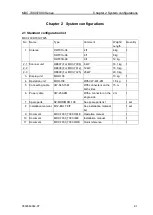
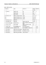
2.4 Option list
No.
Name
Specification
Comment
Weight
/Dimension
/Quantity
1
Gyro converter
S2N, U/N 9028C
qwerty-electronic
2
Log pulse NMEA
converter
L1N, U/N 9181A
qwerty-electronic
200pulse/NM only
3
Gyro / Log interface
ADPC-101
1.5 kg
4
Rectifier unit
PS-010
5A fuse attached
3.5 kg
VL-PSG001
For RW701B-09
5
AC power cable
VV-2D8-3M
Without connectors on the both
sides
3 m
6
Junction box
JB-35
With CW-376-5M
7
Connecting cable
CW-373-*
*: 5M, 10M or 30M
With 6-pin water resistant
connectors at both ends (cable
for data)
5 m, 10 m
or 30 m
CW-374-5M
With a 6-pin connector (1006
series) and a 6-pin water
resistant connector (cable for
data)
5 m
CW-376-5M
With a 6-pin water resistant
connector and one end plain
(cable for data)
5 m
CW-387-5M
With a 8-pin water resistant
connector and one end plain
(cable for AIS)
5 m
CW-561- *
*: 10M or 30M
With 12-pin water resistant
connectors at both ends (cable
for remote display)
10 m or 30 m
CW-576-0.5M
With a 10-pin water resistant
connector and D-Sub connector
(analog RGB) + Alarm out
0.5 m
CW-401- *
*: 5M or 10M
Operation unit cable
5 m or 10 m
8
Antenna-Scanner unit
and Display unit
connecting cable
CW-845-*
*: 20M, 30M, 40M, 50M,
65M or 100M
With connectors on both sides
20m, 30m,
40m, 50m,
65m or 100m
CW-845-XM
100 m Max.
(Designated)
Содержание MDC-7006
Страница 1: ......
Страница 2: ......
Страница 44: ...Chapter 3 installation method MDC 7000 7900 Series 3 24 0092669002 07 Unit mm inch MRM 108 ...
Страница 96: ... This page intentionally left blank ...
Страница 134: ... This page intentionally left blank ...
Страница 155: ...0092669002 07 A 1 INTER CONNECTION DIAGRAM RB807 ...
Страница 156: ...A 2 0092669002 07 INTER CONNECTION DIAGRAM RB808 ...
Страница 157: ...0092669002 07 A 3 INTER CONNECTION DIAGRAM RB809 ...
Страница 158: ...A 4 0092669002 07 INTER CONNECTION DIAGRAM MRD 108 MRO 108 ...
Страница 159: ...0092669002 07 A 5 INTER CONNECTION DIAGRAM MRM 108 MRO 108 ...
Страница 160: ......

