background image

3-14

A-61159   May 2002

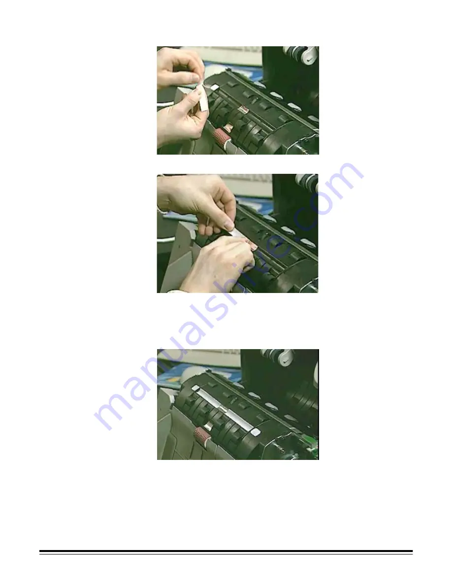
13. Remove the backing from the new blotter strip. 

14. Align the blotter strip in the transport channel. 

Make sure that you align the blotter strips in the transport channel 
before pressing the adhesive side into the channel.

15. Press the blotter strip firmly into the channel.

16. Repeat Steps 13-15 for the other three blotter strips. 

17. Close the pod firmly.


Содержание 3520D - Digital Science

Страница 1: ...Scanner 3000 4000 Series User s Guide A 61159...

Страница 2: ...tandard Configurations 1 7 Maintenance Troubleshooting Features 1 7 Paper Transport Speed Capacity Throughput 1 8 Scanner 3500 1 8 Scanner 3510 1 8 Scanner 3520 1 8 Color Scanner 3590C 1 8 Color Scann...

Страница 3: ...alling an Ink Cartridge 3 8 Setting the Printer Position 3 10 Document Printing Problems 3 11 Document Printer Maintenance 3 11 Expected Life of Document Printer Components 3 11 Replacing an Ink Cartr...

Страница 4: ...3510 and 3520 and Color Scanners 3590C and 4500 4 15 Calibrating the Scanner 4 17 Color Adjustment 4 18 5 Maintenance 5 1 Expected Life of Customer Replaceable Wear Parts 5 1 Lowering the Pod 5 2 Clo...

Страница 5: ...Calibrating the Scanner 6 5 Downloading Firmware 6 7 Error Log 6 8 Service Log 6 9 Selecting a Driver 6 10 7 Troubleshooting 7 1 Indicator Lights 7 1 Clearing Document Jams 7 2 Color Image Quality 7...

Страница 6: ...e Diagnostic Software Diagnostic Software is included on the CD that is packed with each scanner NOTES The software screens shown in this guide are examples from the Diagnostic Software Your software...

Страница 7: ...end of the illumination lamp behind the side access door Refer to Replacing Lamps in Chapter 5 Maintenance for pictures that show the exact locations of this label in your scanner This label is attach...

Страница 8: ...nformation please contact your local authorities or visit the Electronics Industry Alliance web site at www eiae org The product packaging is recyclable Parts are designed for reuse or recycling Safet...

Страница 9: ...kely to cause harmful interference in which case the user will be required to correct the interference at his own expense For Japan This equipment is in the Class A category Information Technology Equ...

Страница 10: ...only exclusive Kodak image processing technology that captures and automatically deskews scanned images resulting in consistent high quality image output at production speed SCSI 2 connectivity Autom...

Страница 11: ...0DP is used as a constant reference to compensate for changes in lamp brightness Pixel and color correction for the best color image quality Multiple color tables available from within the Diagnostic...

Страница 12: ...aceable lamps rollers and other wear parts Easy one step paper jam clearance User accessible error logs via the Kodak Digital Science Diagnostic Software that is included on the CD that is packed with...

Страница 13: ...ppm letter size or A4 landscape oriented 200 dpi 57 ppm letter size or A4 landscape oriented 300 dpi Color Scanner 3590C 75 ppm mixed size landscape oriented 200 dpi bitonal or 100 dpi color output 50...

Страница 14: ...d spectrum of document types found in the most common business applications Optimal scanner performance is achieved when scanning documents within the recommended document specifications listed below...

Страница 15: ...essfully Paper Inks for Scanned Documents NOTE All inks on the paper must be dry before scanning is started Standard offset printing Inkjet printer Thermal transfer Handwriting inks Acceptable Paper C...

Страница 16: ...ors 4 Separator roller 5 Front imaging guide 6 Front lamp 7 Rear imaging guide 8 Rear lamp 2 8 7 6 3 3 4 5 3 1 2 1 Release latch 2 Feed module 3 Input tray extender 4 Pod 5 Output tray 6 Indicator lig...

Страница 17: ...Scanner Unpacking the Scanner NOTE Save all packing materials 1 Carefully cut the tape 2 Open the box 3 Remove the output tray and set it aside 4 Remove the foam cover and set it aside 5 Open the bag...

Страница 18: ...e Now document that is taped to the top of your scanner SCSI Connection Two SCSI 2 50 pin high density D Shell connectors are provided on the rear panel for SCSI connectivity A switch is provided on t...

Страница 19: ...SCSI ID number For most applications this number should be set to 1 NOTE The scanner should be the only device in the SCSI chain If you change the SCSI ID number after installation reboot your PC 3 Co...

Страница 20: ...ide the United States and Canada where appropriate the user or the scanner supplier shall supply an appropriately rated power cord to attach to the scanner Attaching the Output Tray 1 Align the output...

Страница 21: ...61159 May 2002 2 5 Lowering the Deflector 1 Locate the deflector 2 Pull the deflector down 3 Lower it onto the output tray NOTE When scanning lightweight documents that tend to curl raise the deflecto...

Страница 22: ...e IMPORTANT The TWAIN compatible and ISIS compatible device drivers are loaded from within the Diagnostic Software If you are installing the Diagnostic Software in Windows 95 Microsoft Internet Explor...

Страница 23: ...ed with the Scanner 3520DP and Color Scanner 4500DP is unique in that the document print string can be configured to include both literal static information i e information that stays the same for eac...

Страница 24: ...s five characters of the 40 character limit Control of the Printer any combination of dynamic and static fields is allowed as long as the total print string does not exceed 40 characters There is no d...

Страница 25: ...the print string other than automatic sequential number advances require a host SCSI command to restart the printer You must initiate a change between documents or batches Changes cannot be done auto...

Страница 26: ...iption Maximum lines 1 Print locations horizontal 18 manually set Print locations vertical Set by host Print orientation Cine Comic Font size 2 selectable normal and small Ink cartridge HP51604A or co...

Страница 27: ...Message allows you to enter a text message that will be printed The number of characters allowed depends on the number of characters specified in the print string Date Delimiter allows you to specify...

Страница 28: ...you to release the door 3 Lift the printer access door and set it aside WARNING The printer access door must be in place and closed during scanner operation except when changing the printhead location...

Страница 29: ...rt a straightened paper clip into the larger hole on the top of the ink cartridge 3 Rotate the ink cartridge until the bottom is face up 4 Gently press the paper clip against the side of the ink bladd...

Страница 30: ...retailer near you 1 Open the printer access door on the top of the scanner refer to Opening the Printer Access Door in this chapter 2 Slide the green ink cartridge carrier out of its slot 3 Raise the...

Страница 31: ...section Setting the Printer Position 8 Replace the printer access door and close it WARNING The printer access door must be in place and closed during scanner operation except when changing the print...

Страница 32: ...er Make sure that the printer is in the correct position for your documents 1 Locate the printer positioning slots 2 Determine which position is suitable for your printing needs 3 Slide the green ink...

Страница 33: ...ll printer connectors are securely fastened and that the printer cables are not folded or creased Verify that the printer has been enabled through the Diagnostic Software and that the expected print s...

Страница 34: ...ink overflow They should be replaced as necessary Replacement blotter strips are included with the Scanner 3520DP and Color Scanner 4500DP To order additional ink blotter strips refer to Appendix B S...

Страница 35: ...surface 6 Grasp the pod with one hand 7 Pull the release latch with the other hand 8 Gently lower the pod 9 Locate the four ink blotter strips two short two long 10 Grasp a blotter strip and carefull...

Страница 36: ...tter strip in the transport channel Make sure that you align the blotter strips in the transport channel before pressing the adhesive side into the channel 15 Press the blotter strip firmly into the c...

Страница 37: ...n the top of the scanner refer to Opening the Printer Access Door in this chapter 2 Slide the green ink cartridge carrier out of its slot 3 Raise the locking bar if it is not already in a raised posit...

Страница 38: ...ink cartridge carrier back into its slot 10 Replace the printer access door and close it WARNING The printer access door must be in place and closed during scanner operation except when changing the...

Страница 39: ...st 30 seconds the scanner is ready to begin scanning IMPORTANT Always power up the scanner to its ready state before powering up the host computer Starting and Stopping Scanning Before you start scann...

Страница 40: ...es for size type quantity etc in Chapter 1 General Information For faster throughput feed documents into the feeder in landscape orientation longer side as the leading edge 1 Align the leading edges o...

Страница 41: ...function that enables faster scanning of documents that are the same size length and width When enabled this function speeds the scanning of same size documents by approximately 13 Same size document...

Страница 42: ...able the same size documents scanning function 1 Click on the Same Size Documents check box to remove the check mark 2 Click on OK Manual Feeding Follow the guidelines for document size type weight qu...

Страница 43: ...e button this provides more clearance to ease document feeding Business Cards Feed business cards manually by placing them directly under a feed roller on either side of the feed module NOTE You canno...

Страница 44: ...patch code and switches to the opposite scan mode If the scanner is in color scan mode the patch code causes a switch to bitonal scanning if the scanner is in bitonal scan mode the patch code causes a...

Страница 45: ...d be on the patch document Skew tolerance 20x Read rate 99 Dimensions Height 2 5 cm 1 0 in Width of narrow elements 0 175 cm 0 07 in 10 Width of wide elements 0 45 cm 0 18 in 10 Quality Reflectance of...

Страница 46: ...rk appears 2 Click on OK 3 Obtain a laser printed patch document NOTE The patch document pdf file is on the Installation CD 4 Feed a patch document in the correct orientation with your documents into...

Страница 47: ...A 61159 May 2002 4 9 Disabling Patch Detection Click on the Enable Color Patch Detection check box to remove the check mark...

Страница 48: ...cted alarm volume must be set higher than 0 see Step 3 When enabling multifeed detection you can choose to detect a multifeed by length set the alarm volume choose whether scanning is to stop when a m...

Страница 49: ...nning check box for an alarm tone that sounds when a multifeed is detected Settings range from 0 volume off to 15 the loudest volume 4 Click on OK Disabling Multifeed Detection for the Scanner 3500 To...

Страница 50: ...nabling multifeed detection you can choose to detect a multifeed by length and or thickness set the alarm volume choose whether scanning is to stop when a multifeed is detected or continue with an aud...

Страница 51: ...to the enable position 6 Replace the feed module by aligning the pins and fitting it into position 7 Close the pod firmly The remainder of the multifeed detection enabling occurs in the scanning softw...

Страница 52: ...defining a multifeed detection length limit it is recommended that you set the limit at least 0 7 inches 18 mm longer than the length of the documents you are scanning 15 Choose the scanning action t...

Страница 53: ...Scanners 3590C and 4500 Multifeed detection is disabled partly on the scanner itself and partly in the scanning software 1 Remove any documents from the feeder 2 Lower the pod 3 Remove the feed modul...

Страница 54: ...ton to the disable position 6 Replace the feed module by aligning the pins and fitting it into position 7 Close the pod firmly 8 Click on the Thickness Detection Enable check box to remove the check m...

Страница 55: ...llow this procedure 1 Clean both imaging guides Refer to Imaging Guides in Chapter 5 Maintenance 2 Wait three minutes after the pod has been closed to allow the lamps to warm up 3 Obtain a proper cali...

Страница 56: ...Diagnostic Software 6 Click on the button for the calibration mode you wish to use A message appears 7 Insert the calibration target into the scanner 8 Click on OK Calibration begins A confirmation b...

Страница 57: ...eliability across the broadest range of document types sizes and thicknesses Expected life figures are offered as guidelines for operations that follow the recommended scanner cleaning procedures in t...

Страница 58: ...5 2 A 61159 May 2002 Lowering the Pod 1 Power down the scanner 2 Disconnect the power cord 3 Remove the output tray...

Страница 59: ...Grasp the pod with one hand 7 Pull the release latch with the other hand 8 Gently lower the pod NOTE The pod does not have to be lowered completely in order to clear a document jam refer to Clearing...

Страница 60: ...are using the document printer Scanner 3520DP or Color Scanner 4500DP only 1 Follow all of the steps in Lowering the Pod in this chapter NOTE You do not have to lower the pod completely to remove the...

Страница 61: ...pter 2 Remove the feed module by pushing it to the right and lifting it out 3 Place the feed module on a flat surface with the side tabs up 4 Press the locking tabs one on each side and pull the upper...

Страница 62: ...on the side of the tire It makes no difference in which direction the arrows point Do not overstretch the tire it may tear Make sure that the tire is centered on the core and is lying flat on the cor...

Страница 63: ...abs on the lower housing with the rear tabs on the upper housing 11 Press the upper and lower housings together until they snap into place 12 Replace the feed module by aligning the pins and fitting i...

Страница 64: ...981 Use of any other cleaning materials could damage your scanner NOTE Clean the rollers daily if you are scanning carbonless paper or if you are using the document printer Scanner 3520DP or Color Sca...

Страница 65: ...the separator roller by aligning the pins and fitting it into position 7 Close the access cover 8 Close the pod firmly Replacing the Separator Roller Tires 1 Follow all of the steps in Lowering the P...

Страница 66: ...the tire It makes no difference in which direction the arrows point Do not overstretch the tire it may tear Make sure that the tire is centered on the core and is lying flat on the core 6 Insert the...

Страница 67: ...53 5981 Use of any other cleaning materials could damage your scanner NOTE Clean the rollers daily if you are scanning carbonless paper or if you are using the document printer Scanner 3520DP or Color...

Страница 68: ...with a cleaning pad until all residue has been removed 5 Clean any dust or debris in the slots around the drive rollers 6 Close the side access door 7 Replace the feed module by aligning the pins and...

Страница 69: ...als could damage your scanner NOTES Clean the imaging guides daily if you are scanning carbonless paper or if you are using the document printer Scanner 3520DP or Color Scanner 4500DP only During clea...

Страница 70: ...g guide 5 Replace the imaging guide Make sure it is fully seated in its slot 6 Grasp the end of the imaging guide that is in the pod and slowly pull it straight out 7 Wipe the imaging guide with a Sta...

Страница 71: ...ow all of the steps in Lowering the Pod in this chapter 2 Open the side access door 3 Grasp the end of the imaging guide that is behind the side access door and slowly pull it straight out 4 Replace t...

Страница 72: ...5 Grasp the end of the imaging guide that is in the pod and slowly pull it straight out 6 Replace the imaging guide in the pod Make sure it is fully seated in the slot 7 Close the side access door 8...

Страница 73: ...sport Cleaning Sheet CAT No 169 0783 Use of any other cleaning materials could damage your scanner NOTE Clean the paper path daily if you are scanning carbonless paper or if you are using the document...

Страница 74: ...the feeder guides to fit then feed the cleaning sheet adhesive side up twice through the scanner in landscape orientation 5 Using the same cleaning sheet repeat Steps 2 and 3 but feed the cleaning sh...

Страница 75: ...ing carbonless paper or if you are using the document printer Scanner 3520DP or Color Scanner 4500DP only 1 Follow all of the steps in Lowering the Pod in this chapter 2 Remove the feed module by push...

Страница 76: ...g carbonless paper or if you are using the document printer Scanner 3520DP or Color Scanner 4500DP only 1 Follow all of the steps in Lowering the Pod in this chapter 2 Wipe the transport baffles with...

Страница 77: ...identical lamps in the scanner The procedure below shows how to replace the lamp behind the side access door Use the same procedure to replace the lamp in the pod NOTE To order lamps refer to Appendi...

Страница 78: ...5 22 A 61159 May 2002 3 Remove the imaging guide 4 Grasp the green handle of the lamp connector 5 Slightly raise the edge of the black holder and remove the lamp connector...

Страница 79: ...ned facing the imaging guide Use a slight downward pressure as you push the lamp into the scanner This will help the lamp slide in easily 8 Push firmly on the end of the lamp to seat the lamp into the...

Страница 80: ...ner setup process and can be used by scanner operators and system administrators IMPORTANT If you are installing the Diagnostic Software in Windows 95 Microsoft Internet Explorer v4 0 or greater must...

Страница 81: ...tem test A self test checks the image processing hardware in the scanner A scan system test checks the scanner s ability to capture an image In order to perform a self test or scan system test the Dia...

Страница 82: ...6 3 Testing the Scan System 1 Click on Setup and Test in the Diagnostics dialog box The Setup and Test dialog box appears 2 Place a document into the feeder area 3 Click on Scan One Page The document...

Страница 83: ...scanner s date and time to the host computer s date and time 1 Click on Administration in the Diagnostics dialog box A password may be required The Administration dialog box appears 2 Click on Downlo...

Страница 84: ...w this procedure 1 Clean both imaging guides Refer to Imaging Guides in Chapter 5 Maintenance 2 Wait three minutes after the pod has been closed to allow the lamps to warm up 3 Obtain a proper calibra...

Страница 85: ...ment thickness For more information refer to Multifeed Detection in Chapter 4 Using the Scanner For more information about calibration refer to the online help provided with the Diagnostic Software 6...

Страница 86: ...download a firmware file to the scanner 1 Click on Administration in the Diagnostics dialog box A password may be required The Administration dialog box appears 2 Click on Download File 3 Click on the...

Страница 87: ...Error Log The error log in the Diagnostic Software contains information about any errors that have occurred during scanner operations Click on Error Log in the Diagnostics dialog box The current erro...

Страница 88: ...re allows you to log any repairs parts replacement or maintenance performed on the scanner 1 Click on Administration in the Diagnostics dialog box A password may be required The Administration dialog...

Страница 89: ...atible ISIS compatible 1 Click on Administration in the Diagnostics dialog box A password may be required The Administration dialog box appears 2 Click on Select Driver The Select Driver dialog box ap...

Страница 90: ...ver or diagnostic mode Ready Green Scanner is ready to scan normal operation Scanner is not currently scanning or is not ready to scan due to various hardware or software conditions Scanner is powerin...

Страница 91: ...cument and remove it NOTE Avoid getting fingerprints on the imaging guides 4 Close the side access door 5 Close the pod firmly Some jams can be cleared without opening the side access door To clear a...

Страница 92: ...y differ between environments e g in a business document environment images are generally viewed on a monitor whereas in a print on demand environment scanned images are printed To ensure that your sc...

Страница 93: ...e in your scanner A scan system test checks the scanner s ability to capture an image For more information about these tests refer to Testing the System in Chapter 6 Diagnostics NOTE In order to perfo...

Страница 94: ...repack the scanner using the original packaging materials If you do not have the original packaging materials contact your supplier to order a Scanner Relocation Kit CAT No 825 6083 To repack the sca...

Страница 95: ...2 cable from the back of the scanner 5 Remove the output tray and set it aside for now 6 Using two people lift the scanner and place it in the foam base that is inside the box 7 Place the power cord i...

Страница 96: ...A 61159 May 2002 7 7 9 Place the foam cover on top of the scanner 10 Place the output tray on top of the foam cover 11 Close the box The scanner is now ready for moving...

Страница 97: ...Module 250 for documents stacked near the maximum heights listed above you position the batch 12 7 mm 0 5 in away from the baffle housing documents meet specifications for size weight and height of ba...

Страница 98: ...6 Diagnostics and or Chapter 7 Troubleshooting to correct the problem identified in the error log Calibration has failed Make sure that the lamps have been on at least three minutes you are using a pr...

Страница 99: ...pendicular to the feed module documents are being fed in the center of the feeder with the full width of the feeder rollers making contact with all documents the feed module separator roller and paper...

Страница 100: ...le rollers separator roller and drive rollers Refer to Chapter 5 Maintenance The first few color images are very bright Make sure that the lamps have been on at least three minutes then scan the image...

Страница 101: ...anner 3500 200 and 300 dpi bitonal Scanner 3510 200 and 300 dpi bitonal Scanner 3520 200 and 300 dpi bitonal Color Scanner 3590C 200 and 300 dpi bitonal 100 and 150 dpi color Color Scanner 4500 100 an...

Страница 102: ...15 to 76 dry bulb Altitude Up to 2440 m 8000 ft Acoustic Noise Data was measured in accordance with DIN 45 635 ANSI S12 10 1985 and ISO 7779 in a hemi anechoic chamber Scanner 3500 Scanner 3510 and S...

Страница 103: ...Scanner 3510 3520 Color Scanner 4500 159 2195 Kodak Digital Science Separator Roller for Series 3000 4000 Scanners 828 0604 KODAK Separator Roller Type 2 for Series 3000 4000 Scanners 158 8052 Kodak D...

Страница 104: ...taticide Wipes for Kodak Scanners 144 896 5519 Document Printer Supplies Kodak Digital Science Printer Ink Blotters for Series 3000 4000 Scanners 24 12 short 12 long 839 4306 Kodak Digital Science Pri...

Страница 105: ...er 3590C 1 8 Color Scanner 4500 1 8 Scanner 3500 1 8 Scanner 3510 1 8 Scanner 3520 1 8 Capturing image 6 1 Catalog numbers B 1 to B 2 consumables B 1 to B 2 parts B 1 to B 2 supplies B 1 to B 2 Changi...

Страница 106: ...3 5 Date Delimiter 3 5 Defaults 3 5 Enable 3 4 Font 3 5 Message 3 5 options 3 4 to 3 5 Printer Test 3 5 String item selection list 3 5 string text display box 3 4 Y Offset 3 5 Diagnostics 6 1 to 6 10...

Страница 107: ...er 3 1 3 2 Dynamic print field options 3 2 to 3 3 Control of the Printer 3 2 Date 3 2 Sequential Document Number 3 2 Time 3 2 E Electrical requirements A 1 Electromagnetic compliance statements 1 4 EM...

Страница 108: ...to 3 16 characters 3 2 components expected life of 3 11 dynamic information 3 1 3 2 font resolution 3 2 size 3 2 ink blotter strips replacing 3 12 to 3 14 ink cartridge installing 3 8 to 3 9 purging...

Страница 109: ...ption Diagnostic Software 3 5 Minimum document width printer 3 4 Models scanner 1 1 Moving scanner 7 5 to 7 7 Multifeed 7 1 7 10 errors frequent 7 11 Multifeed detection 4 10 to 4 16 button disabling...

Страница 110: ...g 5 2 to 5 3 Poor image quality 7 8 Power cord attaching 2 4 Canada 2 4 Outside U S and Canada 2 4 U S 2 4 down scanner 4 1 7 5 setup 2 4 up scanner 4 1 Preparation document 1 9 to 1 10 acceptable doc...

Страница 111: ...1 Registering scanner 2 6 Repacking scanner 7 5 to 7 7 Replacement parts catalog numbers B 1 to B 2 ordering B 1 to B 2 Replacing feed module tires 5 5 to 5 7 imaging guides 5 15 to 5 16 ink blotter s...

Страница 112: ...er 2 3 ID switch 2 2 2 3 target ID number setting 2 3 Selecting device driver 6 1 6 10 scanner settings 6 1 Self test 6 2 7 4 performing 6 2 Sensor failure 7 1 Sensors 5 17 to 5 20 cleaning 5 19 Separ...

Страница 113: ...to 5 7 separator roller replacing 5 9 to 5 10 Transport baffles cleaning 5 20 Troubleshooting 7 1 to 7 11 chart 7 8 to 7 11 document printer 3 11 features 1 7 imprinter 3 11 TWAIN driver 2 6 6 10 acc...

Страница 114: ...AK COMPANY Document Imaging Rochester New York 14650 www kodak com go docimaging Kodak Digital Science and the ds monogram symbol are trademarks of Eastman Kodak Company A 61159 5 2002 Eastman Kodak C...

Отзывы: