


8
3.2. Determining installation site
•
The installation site should be easy accessible and free of vibrations and shocks
•
Observe enough clearance above the mounting position, in order to be able to install and remove
the sensing probe:
at least
120 mm
(4.72) for KMT-1, KMT-2 and KMT-3
at least
450 mm
(17.7”) for KMT-4 probe length 165 mm (6.5”) DN65 (2 1/2”) up to DN100 (4”)
at least
600 mm
(23.6”) for KMT-4 probe length 315 mm (12.4”) DN125 (5”) up to DN300 (12”)
at least
750 mm
(30.0”) for KMT-4 probe length 465 mm (18.3”) DN305 (14”) up to DN700 (28”)
•
The ambient temperature should not exceed the value as stated in the specifications
(see page 22) – consider heating by radiation.
•
The fluid should not condense at the installation site. Condensation on the tip of the sensing probe
must be avoided.
•
In compressed air systems, the installation should be downstream of the dryer.
•
Observe the direction of the flow by the installation (see page 11).
•
Observe the required straight pipe lengths up and downstream, in order to warrant the specified
measurement accuracy.
•
The flow meter should be installed as far as possible from any flow disturbance. Valves or check-
valves should be installed in a respective distance from the flow meter.
3.2.1. Process pressure
Because of the measuring principle the thermal mass flow meter KMT is largely independent of the process
pressure and is factory calibrated at a pressure of 7 bar (100 psi) (KMT-1, KMT-2 and KMT-3) or 9 bar (130.5
psi) (KMT-4).
In order to achieve the highest measurement accuracy, the slight dependence on process pressure can be
compensated for in two ways:
•
if the process pressure is stable, by programming the pressure value in the configuration software
(see page 35).
•
in case of strong fluctuations of the process pressure (e.g. 3 to 10 bar (40 to 150 psi)) an external
pressure transmitter can be installed and connected to the pressure-compensation input
(see page 35).
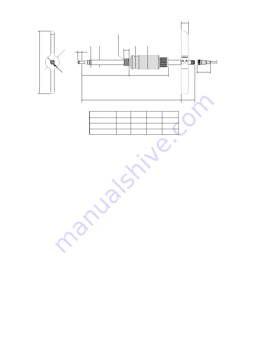
R 1/2“ thread
M12x1 Connector
for probe cable
B
variable insertion depth
max. A
45
(1.77“)
38
(1.5“)
20
(0.79“)
15
(0.59“)
12
(0.47“)
120
(4.72“)
180
(7.09“)
Ø 40
(1.57“)
Ø 13
(0.51“)
Ø 14
(0.55“)
Ø 40
(1.57“)
SW 36
(1.42“)
see accessories for NPT
adapter
3.1.2. KMT-4
Pipe Ø
A [mm] B [mm] A [inch] B [inch]
DN50...DN100
165
285
6.5
11.22
DN125...DN300 315
435
12.4
17.13
DN350...DN700 465
585
18.3
23.03
Содержание KMT-1
Страница 36: ...www kobold com...