Kobold KMT-1 Скачать руководство пользователя страница 22

22

9. 

TECHNICAL DATA KMT-1, KMT-2 and KMT-3

Measuring value


Flow


Measurand 


Volumetric flow at standard conditions acc. DIN 1343 


P

0

 = 1013.25 mbar; t

0

 = 0 °C (273.15 K)


Measuring range 


KMT-x1xx 

 KMT-x2xx


standardized volumetric flow in air


DN15: 

0.32...63 Nm

3

/h 

0.19...37.1 SCFM


0.32...126 Nm

3

/h 

0.19...74.1 SCFM


DN20: 

0.57...113 Nm

3

/h 

0.34...66.5 SCFM


0.57...226 Nm

3

/h 

0.34...133 SCFM


DN25:


0.90...176 Nm

3

/h 

0.53...103.5 SCFM


0.90...352 Nm

3

/h 

0.53...207.1 SCFM


DN32: 1.45...289 

Nm

3

/h 

0.85...170.0 SCFM


1.45...578 Nm

3

/h 

0.85...340 SCFM


DN40 

2.26...452 Nm

3

/h 

1.33...265.9 SCFM


2.26...904 Nm

3

/h 

1.33...531.8 SCFM


DN50: 3.50...700 

Nm

3

/h 

2.06...411.8 SCFM


3.50...1400 Nm

3

/h 

2.06...823.6 SCFM


standardized flow in air, nitrogen, 


argon, CO

2


≤DN50:  0.5...100 Nm/s 

100...19685 SFPM


0.5...200 Nm/s 

100...39370 SFPM


oxygen 

≤DN25:  0.5...100 Nm/s 

100...19685 SFPM


0.5...200 Nm/s 

100...39370 SFPM

 Accuracy 

in air at 7 bar (abs) and 23 °C (73 °F)

1)


± (1.5% of measuring value + 0.5% of full scale)


Accuracy of temperature compensation 

 ± (0.1% of measuring value/°C)


Response time t

90


typ. 1 sec.


Sample rate 


0.5 sec.


Temperature


Measuring range


-20...80 °C 

(-4...176 °F)


Accuracy 

at 20 °C (68 °F)


± 0.7 °C 

(1.26 °F)

Outputs


Output signal and display ranges are freely scalable


Analogue output 

voltage 

0 - 10 V 


  max. 1 mA


current (3-wire) 0 - 20 mA and 4 - 20 mA  R

L

<500 Ohm


Switching output 


potential-free max. 44 VDC, 500 mA switching capacity


Pulse output 


Totalizator, pulse length: 0.02...2 sec.


Digital interface 


USB (for configuration)

Input


Optional pressure compensation   

4 - 20 mA (2-wire; 15 V) for pressure sensor

General

Supply voltage 

18 - 30 V AC/DC

Current consumption 

max. 200 mA (with display)

Temperature range 

ambient temperature:  

-20...60 °C 

(-4...140 °F)


medium temperature:  

-20...80 °C 

(-4...176 °F)


storage temperature: 

-20...60 °C 

(-4...140 °F)

Nominal pressure 

up to 16 bar 

(232 Psi)

Humidity 

no condensation

Medium 

compressed air or none corrosive gases

Connection 

cable gland M16x1.5 (optional connector M12x1 8pol.)

Electromagnetic compatibility 

EN61326-1 

EN61326-2-3 


Industrial Environment

Material 

housing 

metal (AlSi3Cu)


probe 

stainless steel


sensor head 

stainless steel / glass


measurement ball valve 

brass

Housing protection class 


IP65 / Nema 4


1)  The accuracy statement includes the uncertainty of the factory calibration with an enhancement factor k=2 (2-times standard deviation). The accuracy was  


 culated in accordance with EA-4/02 and with regard to GUM (Guide to the Expression of Uncertainty in Measurement).

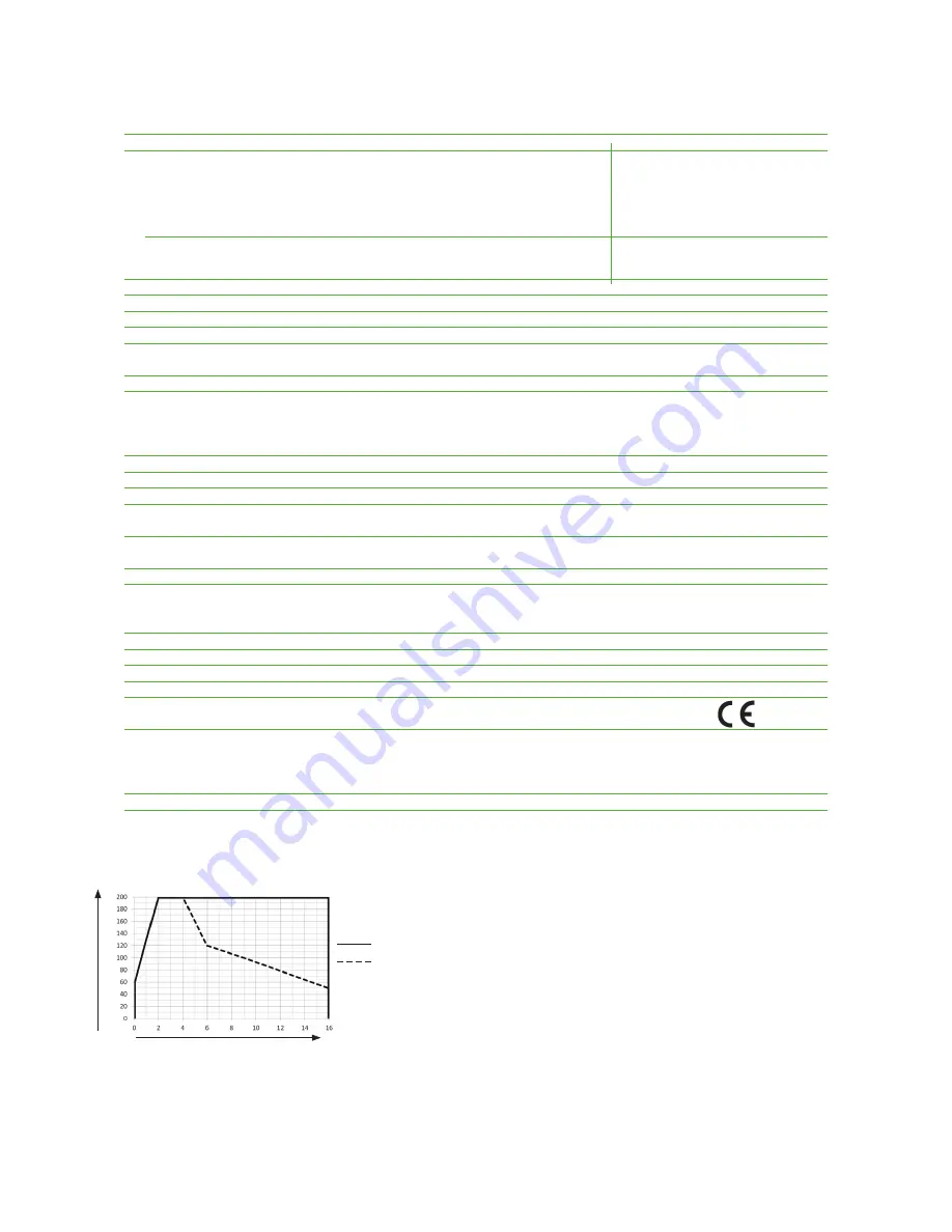
Flow measuring range in dependence on operating pressure 

air, nitrogen, oxygen, argon

CO

2

Formula for calculating the standardized 

volumetric flow:

Q

N

 = V

N

 * id

2

 * π/4 * 3600

Q

N

 ... standardized volumetric flow [m

3

/h]

V

N

 ... standardized flow [m/s]

id ... inner pipe diameter [m]

π ... 3.1415

Nm/s

operating pressure [bar]

Содержание KMT-1

Страница 1: ...Manual Hardware and Software BA_KMT_e V5 1 technical data are subject to change 193624 Thermal Mass flow meter for COMPRESSED AIR and GASES Model KMT...

Страница 2: ...he installation manual may cause harmful interference to radio communications However there is no guarantee that interference will not occur in a particular installation If this equipment does cause h...

Страница 3: ...4 Reset of the consumption counter or the MIN MAX value 19 5 3 5 Maximum consumption counter 19 6 ERROR MESSAGES 20 7 MAINTENANCE 20 7 1 Cleaning of the sensor of the flow meter 20 8 REPLACEMENT PARTS...

Страница 4: ...o be installed in a pressurized system up to PN16 is 16 bar 230 psi For KMT 1 KMT 2 and KMT 3 Prior to the start of the installation the system has to be depressurized Before the installation or remov...

Страница 5: ...Disconnect the device from power supply before opening or closing to avoid damages Do not put a damaged product into operation and make sure that that does not happen inadvert ently A malfunction of t...

Страница 6: ...ch the nominal size of the pipe The measurement valve with shut off function allows for the instal ment and removal of the sensing probe with only interrupting the process flow for a short moment The...

Страница 7: ...ll even if it is released Seal By means of an encapsulated O ring no compressed air can escape under pressure during assem bly Precise positioning The precise positioning with respect to immersion dep...

Страница 8: ...ement accuracy The flow meter should be installed as far as possible from any flow disturbance Valves or check valves should be installed in a respective distance from the flow meter 3 2 1 Process pre...

Страница 9: ...Mounting sensor downwards Horizontal Mounting sensor across 3 3 Installation position Make sure that the arrow on the tip of the sensing probe is pointing in the direction of the flow recommended inst...

Страница 10: ...disturbance of the flow are for instance reducers elbows T pieces valves gate valves etc The specified measurement accuracy can be achieved only when the following straight inlet and outlet pipe leng...

Страница 11: ...nt pin Flow Direction 3 5 2 Assembly without flow meter but with screw cap instead blind cap In order to use the measurement section without the flow meter the blind screw cap in the scope of supply m...

Страница 12: ...flowmeter is therewith completed Flow Direction 3 5 4 Installation of the flow meter sensing probe The flow direction is indicated with an arrow on the tip of the probe Due to the alignment pin is the...

Страница 13: ...on nipple in combination with the 1 2 ball valve The same basic principles apply to installation with the tapping sleeve Pull the measurement sensor back into the non return protection device as far a...

Страница 14: ...direction arrow on the sensor head or the mark on the mounting handle is pointing in the media flow direction The measurement sensor is aligned with precision in the flow direction using the mounting...

Страница 15: ...ess the actual inner diameter of the pipe must be set with the Configurator Software see page 35 Table 1 Factory setting for pipe diameter da di s Nominal diameter External diameter wall thick ness in...

Страница 16: ...cable is needed e g 6 x 1 mm2 AWG 17 4 1 Connection diagram Screw terminal OUT 1 1 for the analogue output is internally connected with GND The housing should be grounded to achieve optimal electroma...

Страница 17: ...cated 5 2 Digital interface USB for configuration The USB connector is behind the blind screw cap at the side of the housing remove the blind screw cap with a screwdriver plug in the USB connector Ins...

Страница 18: ...erature C F V0 Standardized Volumetric Flow m3 h m3 min l min SCFM SLPM m Massflow kg h kg min kg s kg h kg min kg s Q Consumption m3 ft3 p Pressure bar psi 5 3 1 Indication of the analogue and pulse...

Страница 19: ...consumption counter or the MIN MAX value Keep both the UP and DOWN key pressed for 3 sec to enter the menu for resetting the consumption coun ter or the MIN MAX value Select the desired menu item by...

Страница 20: ...gases Cleaning of the sensor is necessary prior to calibration or evaluation 7 1 Cleaning of the sensor of the flowmeter Do not use an abrasive cleaning agent an organic solvent containing halogen or...

Страница 21: ...tapping sleeve DN200 tapping sleeve DN250 tapping sleeve DN300 ERS KMT AN welding nipple stainless steel 1 4301 to be weld at the pipe 25 11 G3 4 18 63 G1 2 26 67 ERS KMT KH ball valve R brass mountin...

Страница 22: ...0 mA RL 500 Ohm Switching output potential free max 44 VDC 500 mA switching capacity Pulse output Totalizator pulse length 0 02 2 sec Digital interface USB for configuration Input Optional pressure co...

Страница 23: ...0 58 kg h DN40 460 46 920 92 kg h DN50 700 70 1400 140 kg h standardized flow DN50 80 8 180 18 Nm s temperature all 30 3 70 7 C US Unit Analogue output 0 10 V 0 4 20 mA from to unit KMT x1 KMT x2 stan...

Страница 24: ...ory calibration with an enhancement factor k 2 2 times standard deviation The accuracy was culated in accordance with EA 4 02 and with regard to GUM Guide to the Expression of Uncertainty in Measureme...

Страница 25: ...0 kg h 125 5 131 7 0 4900 9800 Nm3 h 2800 5600 SCFM 6339 12678 kg h 150 6 159 3 0 7100 14200 Nm3 h 4200 8400 SCFM 9185 18371 kg h 200 8 206 5 0 12000 24000 Nm3 h 7000 14000 SCFM 15524 31049 kg h 250 1...

Страница 26: ...er to set up a smooth installation of the configuration software of the KMT admin authorization for the personal computer is required Place the CD ROM in the drive tray of the computer At this moment...

Страница 27: ...umber for the used USB interface can be found under Start Settings Control Panel System Hardware Device Manager The setting is done under menu Extras and menu item Optional extras Select the COM port...

Страница 28: ...vice is shown here Status message Here are the messages shown about the status and other information Input screen Input screen for the configuration or adjustment of the flow meter Menu tool bar Selec...

Страница 29: ...Output 2 switch relay or pulse output NOTE In case the mode of output 1 is changed the Jumper J1 on the board of the signal conditioning electronics has to be relocated as well see page 29 5 1 2 Measu...

Страница 30: ...ate to open NO activate to close set point 1 Hysteresis When the measurement value reaches set point 1 the relay will be activated The value at the reset point is the value at set point 1 minus the hy...

Страница 31: ...NORMV_MAX m3 h IMPL s 1200 IMPL_MAX IMPW m3 1200 NORMV_MAX m3 h IMPW pulse value m3 IMPL pulse length duration s IMPW_MIN minimum pulse value m3 IMPL_MAX maximum pulse length duration NORMV_MAX expect...

Страница 32: ...alues can be corrected if needed Then the reference value will be uploaded to the flowmeter transmitter and is the adjustment procedure complete The reference point of the customer adjustment must be...

Страница 33: ...t upper adjustment point possibility 1 0 40 of m r 60 100 of m r possibility 2 40 50 of m r 100 of m r possibility 3 0 of m r 50 60 of m r 10 20 30 40 50 60 70 80 90 100 100 90 80 70 60 50 40 30 20 10...

Страница 34: ...mption meter can be reset by clicking the Reset meter button 5 6 Setting up Process Parameters In the tab Process Parameters you can change the Process gas medium and set the pressure compensa tion 5...

Страница 35: ...ransmitter with a 2 wire loop powered 4 20 mA output should be used On the tab Pressure transmitter the measuring range can be entered 5 8 Declaration of Conformance EU Declaration of Conformance We K...

Страница 36: ...www kobold com...

Отзывы: