background image

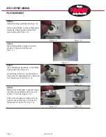
STEP 1

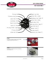
Clean Pilot Block and replace 4 O-rings 

under Selector Knob. Clear holes of any 

obstructions (Fig 1.1).

Apply grease between Selector Knob and 

Pilot body before installing (Fig 1.2).

STEP 2

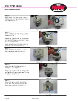
Tighten Lock Nut (Fig 1.3).

STEP 3

Install new O ring on Seat #5473. Make 

sure to use Loctite on threads and tighten 

Seat with screwdriver (Fig 1.4).

Place Booster Spring #5541 on Lower 

Diaphragm Assembly and install (Fig 

1.5). Make sure O ring #5540V is on 

Diaphragm Assembly.

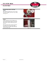
STEP 4

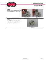
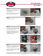
Make sure Lower Diaphragm is aligned in 

bore before securing Lower Cap in place 

use loctite on 3 screws (Fig 1.7).

Tighten 3 screws and check around edge 

to make sure Diaphragm has not shifted 

from bore (Fig 1.8).

www.kimray.com

Page 13

GEN II REPAIR MANUAL

PILOT ASSEMBLY

Figure 1.1

Figure 1.2

Figure 1.3

Figure 1.4

Figure 1.5

Figure 1.6

Figure 1.7

Figure 1.8

Diaphragm

O Ring

Содержание GEN II

Страница 1: ...GEN II Repair Manual...

Страница 2: ...ly 9 Pilot Assembly 13 Pilot Installation 15 Settings 17 NOTE We reserve the right to modify or change without prior notice any statement or information contained herein If exact dimensions or specifi...

Страница 3: ...or it can be used as an interface controller to maintain multiple liquids in a vessel Simply mount controller to vessel set pilot to snap or throt tle and then set level with adjustment knob MAINTENA...

Страница 4: ...F 30 to 260 C APPLICATION Crude Oil Gas Production High heat Steam Flood Production Chemicals corrosion inhibitors Amine Sweetener Systems Gasoline Diesel Fuel Oil Systems FLUID GAS Crude Oil Gas Prod...

Страница 5: ...04 Pivot Post 5505 Lens Gasket 5506 2 Req d Lens Retaining Ring 5509 2 Req d Snap Ring 941 Snap Ring 941 AVariable Link Knob Assy 5493 Plug 699SS6 3 Req d Apply 15 ft lbs Using manual torque wrench wh...

Страница 6: ...n spring then slide Adjustment Lever off Fig 1 7 and Fig 1 8 1 Slide out 2 Slide back STEP 6 Remove Pivot Plate Screws and pull Pivot Rod out Fig 1 9 and Fig 1 10 Remove Screws STEP 7 Remove Coupling...

Страница 7: ...ch around housing Fig 1 13 Pull Terminal Arm out from mounting housing Fig 1 14 STEP 9 Remove Retaining Nut from Arm and dis card O ring and seal Fig 1 15 www kimray com Page 5 GEN II REPAIR MANUAL Te...

Страница 8: ...www kimray com Page 6 GEN II REPAIR MANUAL NOTES...

Страница 9: ...m and tighten Fig 1 3 Loctite STEP 3 Apply Blue Loctite to arm post and tighten Fig 1 4 Loctite STEP 4 Install adjustment assembly and spring assembly Put adjustment arm on first then rotate back to a...

Страница 10: ...g 1 9 STEP 6 Insert Pivot Rod Fig 1 10 Make sure Pivot Rod moves freely does not bind Terminal Arm Assy Install Pivot Plate be sure to use Loctite on screws Fig 1 11 GEN II REPAIR MANUAL Terminal Arm...

Страница 11: ...Lock Washer 4543 Thumb Screw 6780 Selector Pin 5483 Spring 5541 Screw 4918 2 Req d O Ring 647V 2 Req d Diaphragm Assy 7102AS Actuator Assy 7096AS STEP 1 Remove 2 flat head screws from Pilot and remove...

Страница 12: ...t STEP 5 Remove 3 Retaining Screws on Lower Cap and remove Fig 1 6 and 1 7 STEP 6 Remove Lower Diaphragm watch for Spring to fall out Fig 1 8 Diaphragm may be stuck do not pry with screwdriver To remo...

Страница 13: ...g 1 10 and 1 11 STEP 9 On Selector Knob make sure holes are clear These holes connect to one another so blow air in to them in order so see if pathway is clear Fig 1 12 www kimray com Page 11 GEN II R...

Страница 14: ...www kimray com Page 12 GEN II REPAIR MANUAL NOTES...

Страница 15: ...wdriver Fig 1 4 Place Booster Spring 5541 on Lower Diaphragm Assembly and install Fig 1 5 Make sure O ring 5540V is on Diaphragm Assembly STEP 4 Make sure Lower Diaphragm is aligned in bore before sec...

Страница 16: ...1 12 As with lower side it is very important to make sure the Diaphragm sits in bore and not hanging over bore Fig 1 13 STEP 8 Making sure Diaphragm is aligned place top Cap over assembly and secure...

Страница 17: ...rew driver as when removing it Fig 1 4 Pull out Adjustment Knob and slide on to end of Tangent Arm and position pin in hole it was removed from Fig 1 5 STEP 3 If vertical controller Install coupling o...

Страница 18: ...www kimray com Page 16 GEN II REPAIR MANUAL NOTES...

Страница 19: ...Gen II Fig 1 3 Set level so that 3 4 of float is underwater before you receive output STEP 4 Adjustment Knob is left hand thread If Liquid Level is to low turn Adjustment Knob clockwise to allow more...

Страница 20: ...rm same test as for Throttle mode with Float and Adjust Spring if necessary with reverse threaded Adjustment Knob Fig 1 6 When finished remove Float at Coupling and remove all air lines and gauges Ret...

Страница 21: ...www kimray com GEN II REPAIR MANUAL NOTES...

Страница 22: ......

Отзывы: