


www.kimray.com
Page 1
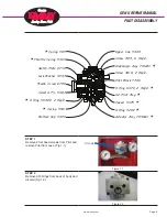
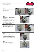
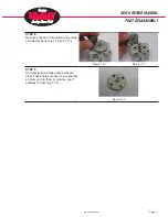
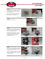
GEN II REPAIR MANUAL
INTRODUCTION
SCOPE
This repair manual contains information for the GEN-II Liquid Level Controller. Included is detailed instruc-
tions in regard to its unique pilot.
DESCRIPTION
The GEN-II Liquid Level Controller uses a spring loaded float to operate a 3 way valve or pilot. This revolu-
tionary pilot can be set for snap mode or throttle mode with the simple turn of a knob. Controlling vessel liq-
uid level has been simplified with 1 control knob to adjust spring tension on float. The pilot assembly is easily
removed by taking out 2 screws. This gives you the choice of repairing the pilot or simply putting a new one
in and repairing the old one at your convenience. Replacement of the pilot assembly can be done in minutes
without taking the controller off line.
The GEN-II is NACE compliant out of the box and comes with a tapped vent hole to pipe bleed gas away.
Side and back npt connections are provided for ease of gas supply and output installation.
OPERATION
The GEN-II uses displacement of a float to control a vessel’s liquid level or it can be used as an interface
controller to maintain multiple liquids in a vessel. Simply mount controller to vessel, set pilot to snap or throt-
tle, and then set level with adjustment knob.
MAINTENANCE
Maintenance should be performed on a regular basis. An initial interval of 12 months is recommended.
Depending on the service conditions and the condition of the controller, the inspection interval may be
decreased or increased. The pilot can be repaired without removing the controller from the vessel, but the
controller will need to be removed for any float related repair.
WARNING
Before performing any service, make sure level controller is isolated from all gas sources. Be sure that all
operating or instrument gas lines have been disconnected.
Never tighten any fittings or the main connections to the level controller while there is pressure in the lines.
NOTE
Because of the how convenient the pilot assembly is to remove and replace, we suggest replacing the pilot
and rebuild old one on bench if a field repair is necessary.
• Use repair kit RMD
To get the long service you have come to expect from Kimray products, always use
GENUINE KIMRAY
PARTS
when doing repairs. Remember, parts made to less than Kimray specifications don’t save you
money!!!
ENG-002.6 Rev. 6 Issued 8-22-2017
Содержание GEN II
Страница 1: ...GEN II Repair Manual...
Страница 8: ...www kimray com Page 6 GEN II REPAIR MANUAL NOTES...
Страница 14: ...www kimray com Page 12 GEN II REPAIR MANUAL NOTES...
Страница 18: ...www kimray com Page 16 GEN II REPAIR MANUAL NOTES...
Страница 21: ...www kimray com GEN II REPAIR MANUAL NOTES...
Страница 22: ......