


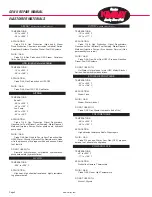


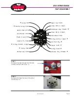


Screw 2213
Pivot Plate 5442
Mounting Piece 5528
Case 5444
Cover 5445
Gasket 5446
Lens 5447, 2 Req’d.
Terminal Arm 5452
Ext. Rod Assy. 5453V
Coupling 5454
Ext. Housing 5455
Wire 5458
Retainer 5459
Pivot Rod 5460
Float 5461
5462 Gauge, 2 Req’d.
Latch 5463
Adj. Lever 5465
Tangent Arm 5466
Spring Assy 5467A
Screw 5468, 2 Req’d.
O Ring 855V (Not Shown)
Screw 5484, 4 Req’d.
Screw 5485
Filter 5486
Link Body 5489
Link Cap 5490
Yoke 5491
Screw 5494
Link Screw 5495
Spring 5496
O Ring 5500V *
Screw 5501
Filter Cap 5502
Arm Post 5504
Pivot Post 5505
Lens Gasket 5506, 2 Req’d.
Lens Retaining Ring 5509, 2 Req’d.
Snap Ring 941
Snap Ring 941
AVariable Link Knob Assy. 5493
Plug 699SS6, 3 Req’d.
Apply 15 ft./lbs.
Using manual torque wrench
when installing 699SS6 plugs
Nut 5531
Decal Left Hand 5521LH
Decal Right Hand 5521RH
Name Plate 5498
NOT SHOWN
Screw 4918, 2 Req’d.
Adjusting Screw 5481
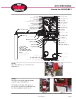
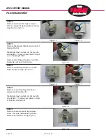
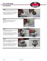
STEP 1
Mount Controller in vise or stand if avail-
able (Fig 1.1).
STEP 2
Open case and inspect Gasket between
cases for rips or tears (Fig 1.2).
If the Gen II is not able to be put on a
stand now is a good time to separate case
by removing Hinge Screw (Fig 1.3).
www.kimray.com
Page 3
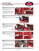
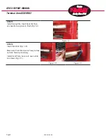
GEN II REPAIR MANUAL
Terminal Arm DISASSEMBLY
Figure 1.1
Figure 1.2
Figure 1.3
Bolt
Содержание GEN II
Страница 1: ...GEN II Repair Manual...
Страница 8: ...www kimray com Page 6 GEN II REPAIR MANUAL NOTES...
Страница 14: ...www kimray com Page 12 GEN II REPAIR MANUAL NOTES...
Страница 18: ...www kimray com Page 16 GEN II REPAIR MANUAL NOTES...
Страница 21: ...www kimray com GEN II REPAIR MANUAL NOTES...
Страница 22: ......