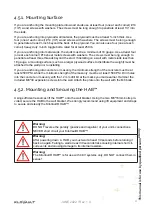
4.6.1. Connecting the HAB™
Step
Description
1
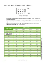
Set the HAB™ address using the address DIP switch (refer to 4.6.7
Setting the HAB™ Address).
2
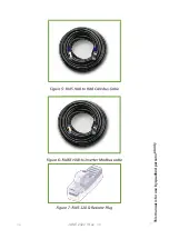
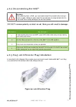
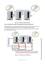
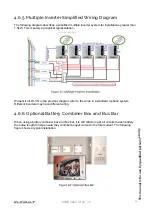
If you have multiple HAB™ units, daisy chain the RJ45 HAB to HAB CAN Bus cable be-
tween each unit. This leaves an empty CanBus port on either end of the string to install
the provided RJ45 120 Ω Resistor Plug. (Refer to Section 4.6.3)
Note:
If a longer cable is needed, it can be replaced with a standard, straight through
RJ45 cable. (10’ Max length)
3
Optional:
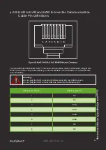
Connect the Modbus communication cable between the Leader HAB™ and
the inverter. Contact KiloVault® for a list of supported inverters.
4
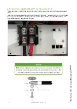
Connect the power cables from the HAB™ to the inverter (or to the DC bus if installing
to multiple units), making sure to use overcurrent protection as required. Torque the
battery cable terminals to 15Nm (11 ft-lb or 132 in-lbs)
Note:
Only 1/0 or 2/0 battery cables are permitted.
5
Close (switch to “On”) the Inverter main DC Breaker.
6
Close (switch to “On”) the battery breaker on the side of the HAB™
7
Press and hold the power button until the red “RUN” LED flashes. (Approx. 3 - 5 sec-
onds).
8
Wait five seconds for the HAB™ units pre-charge function to complete.
9
If installing more than one HAB™ simply repeat steps 7 & 8 until all the units have been
energized.
10
Activate invert function on your inverter, if applicable.
This manual
is f
or
use b
y qualified personnel
onl
y
JUNE 2022 / Rev: 1.0
2022
25
Содержание HAB 7.5
Страница 1: ...INSTALLATION INTEGRATION GUIDE KiloVault HAB SCHNEIDER XW PRO UL9540 Base Kit JUNE 2022 Rev 1 0 ...
Страница 19: ...This manual is for use by qualified personnel only JUNE 2022 Rev 1 0 2022 17 ...
Страница 73: ...JUNE 2022 Rev 1 0 This manual is for use by qualified personnel only 71 ...

