background image

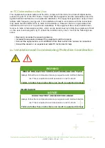
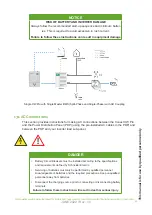
WARNING

RISK OF FIRE,ELECTRIC SHOCK, EXPLOSION, AND ARC FLASH

Always follow the recommended start-up sequence and minimum batter-

ies. This is required to avoid excessive in rush current.

Failure to follow these instructions can result in equipment damage

10. FCC Information to the User

This equipment has been tested and found to comply with the limits for a Class B digital device, 

pursuant to part 15 of the FCC Rules. These limits are designed to provide reasonable protection 

against harmful interference in a residential installation. This equipment generates, uses and can 

radiate radio frequency energy and, if not installed and used in accordance with the instructions, 

may cause harmful interference to radio communications. However, there is no guarantee that 

interference will not occur in a particular installation. If this equipment does cause harmful inter-

ference to radio or television reception, which can be determined by turning the equipment off and 

on, the user is encouraged to try to correct the interference by one or more of the following mea-

sures:

• Reorient or relocate the receiving antenna.

• Increase the separation between the equipment and the receiver.

• Connect the equipment to a circuit different from that to which the receiver is connected.

• Consult the dealer or an experienced radio/TV technician for help.

11. Installation and Commissioning Protection Coordination

Inrush Current

NOTICE

RISK OF BATTERY AND INVERTER DAMAGE

Always follow the recommended start-up sequence and minimum batter-

ies. This is required to avoid excessive in rush current.

Failure to follow these instructions can result in equipment damage

48

JUNE 2022 / Rev: 1.0

For information about operating the Conext XW Pro Inverter/Charger, see the Conext XW Pro Inverter/Charger Owner’s Guide (975-0240-01-01).

Содержание HAB 7.5

Страница 1: ...INSTALLATION INTEGRATION GUIDE KiloVault HAB SCHNEIDER XW PRO UL9540 Base Kit JUNE 2022 Rev 1 0 ...

Страница 2: ... HAB system concepts and installation instructions Details may vary slightly depending upon the market region and the product version This publication could include technical or other inaccuracies or typographical errors Changes are periodically added to the information herein these changes will be incorporated in new editions of the publication KiloVault may make improvements and or changes in th...

Страница 3: ...t HAB 22 4 6 Connecting the KiloVault HAB to Your Inverter 22 4 6 1 Connecting the KiloVault HAB 25 4 6 2 Disconnecting the KiloVault HAB 26 4 6 3 RJ45 120 Ω Resistor Plug Resistor Plug Installation 26 4 6 4 Single Inverter Simplified Wiring Diagram 27 4 6 5 Multiple Inverter Simplified Wiring Diagram 28 4 6 6 Optional Battery Combiner Box and Bus Bar 28 4 6 7 Setting the KiloVault HAB Address 29 ...

Страница 4: ...itial HAB Unboxed Voltage 45 7 1 TroubleShooting 45 7 2 Downloads and Documentation 45 7 3 Software 45 7 4 Contact Us 45 8 1 XW PRO Installation 45 8 2 Audience 45 9 1 Conext XW Pro Features 46 9 2 Single XW Pro with Single LEADER KiloVault HAB Split Phase and Single Phase with AC Coupling 47 10 1 FCC Information to the User 48 11 1 Installation and Commissioning Protection Coordination 49 12 1 Cl...

Страница 5: ...al messages may appear throughout this bulletin or on the equipment to warn of potential hazards or to call attention to information that clarifies or simplifies a procedure Please refer to Firmware Updates on page 36 of this guide Abbreviations and Acronyms Name Abbreviations or Acronyms UNIT KiloVault HAB CEC California Energy Commission CSA Canadian Standards Accociation GT Grid Tie LCD Liquid ...

Страница 6: ...nd animals Warning The KiloVault HAB is heavy over 230 lb 105 kg and may cause serious back injury Lift with multiple people and lifting equipment rated to lift and support at least 230 lb Warning Do not dispose of this product with household waste Caution Risk of electric shock Attention Disconnect the KiloVault HAB before carrying out maintenance or repair Attention Read this instruction manual ...

Страница 7: ... injury or death Warning Never connect KiloVault HAB units in series Warning After powering down a HAB you must wait at least 30 seconds before turning it back on again Failing to wait at least 30 seconds risks causing internal short cir cuit events and causing damage to its internal resistors Caution Risk of electric shock Warning Do not place or install near flammable or explosive materials Warn...

Страница 8: ...s should be observed when handling the HAB 1 3 1 Transportation The HAB should kept horizontal while being moved except when it is being lifted into place for mounting Because the HAB weighs over 230 lb it should be moved with the help of multiple peo ple and moving lifting equipment rated over 300 lb Do not drop the HAB or damage will occur If you are transporting HAB batteries while they are sti...

Страница 9: ...uids and electrical appliances 1 3 4 Qualified Personnel This guide and the tasks and procedures described in this manual are intended for use by qual ified personnel only Only qualified personnel shall install operate overhaul or maintain the HAB During maintenance or overhaul at least two people equipped with protective measures including but not limited to safety glasses insulated gloves and sa...

Страница 10: ...loVault salesperson for details Long cycle life 4000cycles Advanced High Low temperature cycle performance Intelligent LED LCD display Support for up to 14 HAB battery Leader plus 13 Followers modules in parallel The wiring panel of the HAB has been designed for function and convenience The HAB wiring panel has access ports on the left and right sides and the bottom Power and communication cables ...

Страница 11: ...rical Specifications The following specifications describe the HAB system Note Specifications are subject to change without prior notice The following are specifications only NOT set points Item Specification Battery Type LiFePO4 Internal Resistance 15mΩ JUNE 2022 Rev 1 0 2022 9 ...

Страница 12: ...cation protocol CAN Bus HAB to Inverter communication protocol Modbus Canbus High Voltage Cutout 60 0 5 V not a set point Low Voltage Cutout 48 0 V not a set point Maximum Cell Balancing Current 70 mA Maximum Continuous Charge Current 120 A not a set point Maximum Continuous Discharge Current 150 A not a set point Maximum Continuous Discharge Power 7 5 kW Maximum HAB to HAB Cable Length 9 84 ft 3 ...

Страница 13: ...f no activity Item Specification Operational Temperature Range Indoors away from direct exposure to rain or sun Operating Temperature 32 to 113 F 0 to 45 C Recommended Operating Temperature 59 to 95 F 15 C to 35 C Short Term less than one month Storage Tempera ture 4 to 110 F 20 to 45 C Absolute Maximum Altitude 13 123 feet 4000 m To operate the HAB at 3000m limit the output power to max 6 48Kw ma...

Страница 14: ...tem Specification KiloVault HAB Weight 230 lb 105 kg net 286 lb 130 kg gross KiloVault HAB Height 32 in 812 8 mm KiloVault HAB Width 22 5 in 571 5 mm KiloVault HAB Depth 9 2 in 233 7 mm Mounting Plate Height 18 in 458 1 mm Mounting Plate Width 22 3 in 565 5 mm JUNE 2022 Rev 1 0 12 ...

Страница 15: ...Torque 15 Nm 11 06 ft lb 132 76 in lb Large power ports PG42 Approx 2 1 in 55mm Small communication ports PG21 Approx 1 1 in 28mm 3 4 Certifications Cell Certifications o UL1642 o UL9540 o IEC62619 o UN38 3 Complete Unit Certifications o cETLus UL 1973 o UN DOT 38 3 acceleration three times each side o 50 gn for 11 ms o 150 gn for 6 ms o IP54 Vented plates installed o IP55 Solid plates installed o...

Страница 16: ...h of children and animals Warning The KiloVault HAB is heavy over 230 lb 105 kg and may cause serious back injury Lift with multiple people and lifting equipment rated to lift and support at least 230 lb Warning Do not dispose of this product with household waste Caution Risk of electric shock Attention Disconnect the KiloVault HAB before carrying out maintenance or repair Attention Read this inst...

Страница 17: ...nd may be necessary for system configuration or troubleshooting Depending on your HAB unit s position viewing this information after installation may be difficult It may be easier to open the tabs at the bottom along the sides of the box and remove the box from the pallet rather than removing the top lid and lifting the HAB with the handles 4 1 Installation Flowchart The following flowchart provid...

Страница 18: ...ning is high ly recommended There are built in handles o the sides of the HAB to assist when lifting The built in side handle are designed to help lift the battery once up righted but are of only partially helpful while the battery is still laying on it s back At least 2 to 3 people are necessary to lift and upright the battery from its crate The use of heavy gloves is highly recommended Retain al...

Страница 19: ...This manual is for use by qualified personnel only JUNE 2022 Rev 1 0 2022 17 ...

Страница 20: ...ses insulated gloves and protective footwear Lift equipment capable of lifting and supporting at least at least 230 lb 105 kg Drill and drill bit for drilling pilot holes for the mounting plate If you will be mounting onto concrete or masonry you will need a 12 mm drill bit for the in cluded M8 30 expansion screws Conduit and conduit fittings depending upon local electrical requirements Various si...

Страница 21: ... flammable or explosive items Keep out of the reach of children and animals Do not install near a transformer or any other strong electromagnetic field Strong electro magnetic fields can disrupt the HAB communication system Choose a wall capable of supporting the full weight of the HAB over 300 lb with one or more of the following characteristics wood studs at regular intervals plywood sheeting at...

Страница 22: ...This manual is for use by qualified personnel only 4 5 Install the HAB Wall Mounting Plate The HAB comes with the single mounting plate option JUNE 2022 Rev 1 0 20 ...

Страница 23: ...mark your pilot holes on the mounting surface Choose holes so that you can mount the plate using at least four of the widely spaced holes Use a level to ensure that the plate is level Refer to Section 4 5 1 Mounting Surface for information regarding mounting surface requirements JUNE 2022 Rev 1 0 2022 21 ...

Страница 24: ...the weight must be attached to the wall prior to installing If you are anchoring into concrete or masonry the minimum strength of the concrete must be at least 2500 PSI while the minimum strength of the masonry must be at least 1500 PSI Drill holes into the concrete or masonry with the 12 mm drill bit at the marks you made earlier Hammer the included M8 30 expansion screws into the wall Attach the...

Страница 25: ...se them remove the plugs from the relevant access ports and replace them with the included strain reliefs The large strain relief will accept up to 2 0 wire 4 6 Connecting the HAB to Your Inverter NOTE Note When making the connections be sure to observe correct hard ware stacking and proper polarity and ensure that nothing obstructs the connection between the terminal surface and the battery cable...

Страница 26: ...loVault HAB is provided with ground terminals that must be reliably connected to ground protective earth by appropriately sized equipment grounding conductors System grounding for the AC and DC systems must be done according to all applicable NEC and local installation codes To connect the HAB to the DC grounding system use the ground lug at the bottom of the chassis see Figure below The terminal ...

Страница 27: ...supported inverters 4 Connect the power cables from the HAB to the inverter or to the DC bus if installing to multiple units making sure to use overcurrent protection as required Torque the battery cable terminals to 15Nm 11 ft lb or 132 in lbs Note Only 1 0 or 2 0 battery cables are permitted 5 Close switch to On the Inverter main DC Breaker 6 Close switch to On the battery breaker on the side of...

Страница 28: ...nnecting more than one HAB power off the other units one by one by pressing each unit s power button 2 Set the disconnect switch on the side of the HAB to the OFF position 3 Disconnect all communication cables as applicable 4 Disconnect the DC power cables from the HAB to the inverter or to the DC bus as appli cable making sure to use overcurrent protection as required 4 6 3 RJ45 120 Ω Resistor Pl...

Страница 29: ...stem and may not include all the safety equipment required by regional authority This is purely a graphical representation It is extremely important to make all conductors to each battery the same length to help ensure they contribute balanced current JUNE 2022 Rev 1 0 120 Ω ResistorPlug 120 Ω ResistorPlug 120 Ω ResistorPlug 120 Ω ResistorPlug 2022 27 ...

Страница 30: ...s G L3 L2 L1 N in the previous diagram refer to the wires in a standard 3 phase system Different inverters may have different wiring 4 6 6 Optional Battery Combiner Box and Bus Bar When using a battery combiner box and bus bar it is still critical to get all circuits to each battery the same length to help ensure they contribute equal current to the total current The following figure shows a typic...

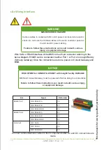
Страница 31: ...han one HAB and connecting them with the communication cable the Leader address must be on off off off Module Number DIP Switch Settings Switch 1 Switch 2 Switch 3 Switch 4 Leader Singles KIloVault HAB OFF OFF OFF OFF Leader Multiple KIloVault HAB ON OFF OFF OFF 1st OFF ON OFF OFF 2nd ON ON OFF OFF 3rd OFF OFF ON OFF 4th ON OFF ON OFF 5th OFF ON ON OFF 6th ON ON ON OFF 7th OFF OFF OFF ON 8th ON OF...

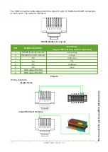
Страница 32: ...The provided battery to inverter Modbus communication is a custom RJ485 non standard Warning Do not plug the HAB to Inverter Modbus cable into the CAN Bus port Do not plug the HAB to HAB CAN bus cable into the Modbus port CAN Bus Pin Number CAN Bus Definition 1 NC 2 NC 3 CANL 4 CANL 5 CANH 6 CANH 7 NC 8 NC This manual is for use by qualified personnel only JUNE 2022 Rev 1 0 30 ...

Страница 33: ...6 NC 7 BMS debug RS485A 8 BMS debug RS485B 5 Operation Maintenance Monitoring 5 1 HAB Control Panel The KiloVault HAB control panel displays a variety of useful information regarding the operation of your system This manual is for use by qualified personnel only JUNE 2022 Rev 1 0 2022 31 ...

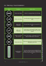
Страница 34: ...h a local connection Flashing The status can be checked only through the unit s Wi Fi hotspot using the mobile application On Steady Normal Wi Fi status Number of semi circles 1 to 3 indicates the Wi Fi signal strength Alarm or Warning Indicators The HAB will light these indicators when a warning or alarm condition occurs HV Battery High Voltage LV Battery Low Voltage HT Battery High Temperature L...

Страница 35: ...oltage rises above 49 6 V 5 V o If a high voltage alarm occurs you can ignore it You will still be below the high voltage protection Note If this does occur the alarm will not clear until the voltage falls below 54 4 0 5 V The HAB unit s SoC and capacity should now be calibrated 5 3 Charging Settings Your battery charger solar inverter or AC should be set to stop charging at a maximum voltage and ...

Страница 36: ... Equipment LBCO Low Battery Cut Out 48 2 V 48V for Schneider Equipment LBCO Delay 3 seconds LBCO Hysteresis 2 V Max Bulk Current Set to whatever percentage of the inverter current plus the charge controller current is less than or equal to 100 A Absolute Maximum Charge Rate 120A per HAB in Parallel Solar Charge Controller Amps Percentage of Inverter Charger Max DC Output Example For a single HAB s...

Страница 37: ...ate 1C Recharge Rebulk Volts Set to start charging from solar before charging by AC just above the inverter charger s recharge rebulk voltage of 51 4 V Battery Monitor Midpoint Sensor If you are using a battery monitor with midpoint sensors secure the midpoint sensor leads out of the way and electrically isolate the midpoint sensors with electrical tape shrink wrap or any other appropriate method ...

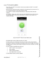
Страница 38: ...n Figure 20 KiloVault HAB iT Basic Screen Slider Switch The status should change to No charge or discharge Figure 20 HAB iT Basic Screen Slider Switch KiloVault HAB firmware updates take about 10 minutes Firmware updates are usually timed to take place during the evening in North America Depending on what part of the BMS is being updated either the red ALARM LED will flash by itself or the red ALA...

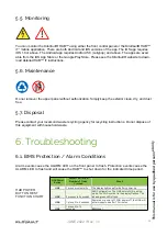
Страница 39: ...ess the HAB unit s power button the control panel will again light for 1 minutes If there is an alarm condition the RED Alarm LED will light plus one or more of the alarm or pro tection state indicators at the right of the control panel will light Please see the BMS Alarm and Protection table for details To turn off the HAB press the power button for three seconds The run LED will flash five times...

Страница 40: ...l solid waste recycling agency for recycling instructions Do not dispose of this equipment with household waste 6 Troubleshooting 6 1 BMS Protection Alarm Conditions Alarm events cause the ALARM LED on the front panel to flash Protection events cause the ALARM LED to flash and will cause the HAB to shut down for the indicated time period HAB Power Button Amount of Time Number of Times Pressed Resu...

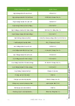
Страница 41: ...or 1s Low Displayed Capacity Alarm 10 of Capacity or lower Low Voltage alarm for each cell 3 00 0 03 V Low Voltage protection for each cell 2 70 0 03 V Delay time 1s Low Voltage release for each cell 3 10 0 03 V Low Voltage alarm for total voltage 48 0 V 0 5 V Low Voltage protection for total voltage 45 5V 0 5 V Delay time 1s Low Voltage release for total voltage 49 6 V 0 5 V Low Voltage release m...

Страница 42: ...C Discharge High Temperature alarm 140 F 5 4 F 60 C 3 C Discharge High Temperature protection 149 F 5 4 F 65 C 3 C Discharge High Temperature release 131 F 5 4 F 55 C 3 C Charge Low Temperature Alarm 37 4 F 5 4 F 3 C 3 C Charge Low Temperature Protection 32 F 5 4 F 0 C 3 C Charge Low Temperature Release 41 F 5 4 F 5 C 3 C Discharge Low temperature alarm 5 F 5 4 F 15 C 3 C Discharge Low temperature...

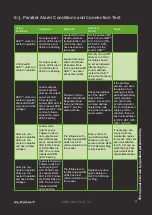
Страница 43: ...ises above the recover tem perature Charge or Discharge Over Current Reduce the charging or discharging current The battery will auto release in one minute Battery Short Circuit Check the external power connections of the battery Eliminate the short circuit Flashing State of Charge Bar The LCD control panel and or the State of Charge light bar have lost connection to the BMS Restart the battery us...

Страница 44: ...o a unique address Restart the units using the front panel power switch If the problem persists you have the option of op erating your bank without interbattery communication You can do this by removing all of the communication cables port ter minators then set each units address to OFF OFF OFF OFF 0 0 0 0 Units are con nected in parallel Units are con nected in parallel and have similar voltages ...

Страница 45: ...ns are lit High voltage units are discharging Low voltage units are not discharging Low voltage RUN LED flashing The low voltage unit has been re moved from parallel connection with the rest of the bank When the rest of the bank is dis charged to within 1 V of the low voltage unit it is added back into parallel connection Normal operation No action needed HABs connected in parallel HABs dischargin...

Страница 46: ...e for iOS and Android mobile devices can be down loaded from both the iOS and Android app stores There is not a desktop version of KiloVault HAB iT 7 4 Contact Us Email info kilovault com Phone 1 888 218 5924 KiloVault LLC 330 Codman Hill Road Boxborough MA 01719 6 5 Initial HAB Unboxed Voltage If your HAB has a low initial voltage when unboxed refer to the following information 6 6 Low HAB voltag...

Страница 47: ...terial ForinformationaboutoperatingtheConextXWProInverter Charger seetheConextXWProInverter ChargerOwner sGuide 975 0240 01 01 8 1 XW PRO Installation This guide provides explanations and procedures for installing Schneider Electric Conext XW Pro inverter charger Before installing the Conext XW Pro Inverter Charger read all instruc tions and cautionary markings in this Guide For information about ...

Страница 48: ...n Use the jumpers to reconfigure the transformer wires For more information see Split Phase to Single Phase Conversion Instructions in this Guide AC1 AC2 Event Equalize kW A Charging Inverting 1 INFORMATION PANEL 2 CONECT XW Pro CHASSIS WITH AC ACCESS PANEL REMOVED INTERNAL COMPONENTS HIDDEN FOR CLARITY 3 AC TERMINAL BLOCK 4 AC GROUND BAR 5 DUAL NESTED KNOCKOUTS 6 POSITIVE BATTERY TERMINAL RED 7 D...

Страница 49: ...ently BMS communication is supported for systems with a single XW Pro inverter and optional AC coupled PV inverters Systems with multiple XW Pro inverters and DC coupled systems with Conext MPPT solar charge controller not currently available with BMS communication future release Systems with multiple XW Pro inverters and or DC coupling with Conext MPPT solar charge controller may be installed wit...

Страница 50: ...ur in a particular installation If this equipment does cause harmful inter ference to radio or television reception which can be determined by turning the equipment off and on the user is encouraged to try to correct the interference by one or more of the following mea sures Reorient or relocate the receiving antenna Increase the separation between the equipment and the receiver Connect the equipm...

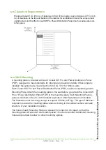
Страница 51: ... Panel PDP requires a separate generic Mounting Plate Attach the mounting plate to the wall before you attach the Conext XW Pro or Power Distribution Panel PDP to the mounting plate Each Mounting Plate re quires a minimum of four inch diameter lag bolts or other fasteners not included The fasteners must be strong enough to support 500 lbs 227 kg The type of fastener required to secure the mounting...

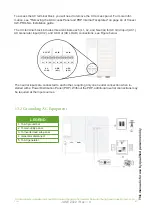
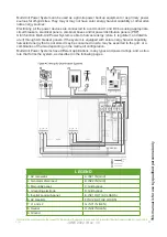
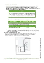
Страница 52: ...wer Distribution Panel PDP using the pre installed AC cables in the PDP and between the PDP and your inverter load sub panel DANGER Battery Circuit Breakers must be installed according to the specifications and requirements defined by Schneider Electric Servicing of batteries must only be performed by qualified personnel knowledgeable of batteries and the required precautions Keep unqualified pers...

Страница 53: ...Figure below AC IN AC OUT GRID AC IN AC1 AC GEN LOAD AC2 N L1 L2 N L1 L2 N L1 L2 AC IN AC OUT AC IN GRID AC1 AC LOAD GEN AC2 N L1 L2 N L1 L2 N L1 L2 The neutral inputs are connected to each other requiring only one neutral connection when in stalled with a Power Distribution Panel PDP Without the PDP additional neutral connections may be required at the input sources 13 2 Grounding AC Equipment LE...

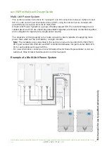
Страница 54: ...the power devices are connected to a common AC and DC bus using appropriate circuit breakers electrical panels combiner boxes and or power distribution panels PDP A full function Multi Unit Power System is able to harvest energy store it regulate it and distrib ute it through AC breaker panels If the system is equipped with solar energy harvest capability harvested energy that is not stored may be...

Страница 55: ...Power System This section provides instructions for making AC and DC connections between multiple Conext XW Pro units and a Power Distribution Panel PDP using the cables that are included with each PDPand Connection Kit for INV2 INV3 PDP Note The installation steps described in this section require a Connection Kit for INV2 INV3 PDP part number 865 1020 02 and PDP 120 240V 60A Breaker Kit part num...

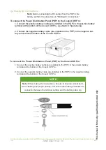
Страница 56: ...ext XW Pro 1 Connect the positive battery cable pre installed in the PDP to the positive battery terminal at the bottom of the Conext XW Pro 2 Connect the negative battery cable pre installed in the PDP to the negative battery terminal at the bottom of the Conext XW Pro NOTE Note When making the connections be sure to observe correct hard ware stacking and proper polarity and ensure that nothing o...

Страница 57: ...ally stacked when paralleling battery cables Recommended Battery Cable Size Versus Length Inverter Model Up to 10 Feet 3M 90 C wire XW Pro 4 0 AWG 120 mm2 Cable Size Required Maximum Breaker Fuse Size 4 0 0000 AWG 120 mm2 250 amps Recommended Battery Cable Size Versus Length 3 Attach the DC terminal covers included with the Conext XW Pro to the bottom of the Conext XW Pro DC terminals Connect your...

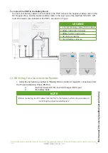
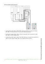
Страница 58: ... battery cable to the input end of the GJ250A 160 VDC 3 8 stud DC breaker pre installed in the PDP as shown in Figure 17 DC Wiring for a Dual Inverter System 1 Using the instructions provided in Making DC Connections make DC connections from the Power Distribution Panel PDP to a the first Conext XW Pro Inverter Charger INV1 and b the battery bank NOTE Before connecting the DC cables from the PDP t...

Страница 59: ... 3 Connect the negative battery cable for INV2 included with the Connection Kit for INV2 INV3 PDP to the DC Negative Bus 4 Connect the positive battery cable to the positive terminal on the second Conext XW Pro INV2 and the negative battery cable to the negative terminal on INV2 DC Connections to Dual Inverter ForinformationaboutoperatingtheConextXWProInverter Charger seetheConextXWProInverter Cha...

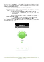
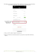
Страница 60: ...you have not done so already download and install the HAB iT mobile app to the mobile device you will use for setting up your HAB a Following the instructions in the HAB iT mobile app manual use the mobile device to connect the Leader HAB to the internet and update it to the latest firmware version b Follow the instructions below to set the Leader HAB to the correct HAB to inverter communication p...

Страница 61: ...ect the Schnieder XW PRO protocol 3 Start your XW Pro Refer To Page 67 of this Manual 4 Make sure that the rest of the Xanbus devices in your system are connected to the Xanbus network Choose 0001 to select the Schnieder XW PRO protocol ForinformationaboutoperatingtheConextXW ProInverter Charger seetheConextXWProInverter ChargerOwner sGuide 975 0240 01 01 ...

Страница 62: ... and cutting wires if needed KiloVault HAB Updated to the most recent firmware using the HAB iT mobile app The HAB iT mobile app Apple iOS https apps apple com us app kilovault hab it id1528264614 Android https play google com store apps details id com kilovault battery V1 V2 Early V3 HABs HAB to Inverter Amphenol AT06 6S Modbus Cable Early V1 HABs cannot be updated through the cloud Contact KiloV...

Страница 63: ...ISO1 CANG ND WARNING XANBUS SHOCK HAZARD Xanbus cables in contact with DC or AC power can transmit an electric shock Do not route the Xanbus cables in the same conduit or panel as the AC and DC power cabling Failure to follow these instructions can result in death serious injury or equipment damage NOTICE RISK OF BMS or CONEXT GATEWAY with Insight Facility DAMAGE BMS and Conext Gateway must be pow...

Страница 64: ...ion Wire Color may be different than what it says below 1 RS485 Inverter Comms white orange 2 RS485A Inverter Comms orange 3 NC white green 4 NC blue 5 NC white blue 6 NC green 7 BMS debug RS485A 8 BMS debug RS485A RS485 Modbus Connector Pinouts Wiring Diagrams Insight Home InsightFacility Gateway ForinformationaboutoperatingtheConextXWProInverter Charger seetheConextXWProInverter ChargerOwner sGu...

Страница 65: ...ll need a special communication cable to connect the V4 with the older HABs Please contact your distributor for the cable 2 For the Insight Home a Connect the pin 1 wire to pin 11 on the Insight Home s 12 pin connector b Connect the pin 2 wire to pin 9 on the Insight Home s 12 pin connector 3 For the Insight Facility a Connect the pin 1 wire to pin 20 on the Insight Facilitiy s 26 pin connector b ...

Страница 66: ... setting changes to the XW Pro put the XW Pro into Standby b Click Setup in the green top horizontal menu i Click Configuration in the left hand vertical menu 1 Click Modbus settings a In Modbus settings Set the Baud Rate to 19200 Parity to none Stop bits to 1 Error limit to 3 Timeout ms to 1000 b Click Apply ii Click Device Detection 1 Click Detect Devices a Set the Range from 1 to 63 Click Detec...

Страница 67: ...green top horizontal menu i Click BMS Setup in the left hand vertical menu 1 Select KiloVault HAB 7 5 as the battery type 2 Input the number of HABs in your battery bank 3 Click Apply e Click Devices in the green top horizontal menu Click Other Devices in the left hand menu 1 Click SECAN_BMS_0 2 Click Configuration 3 Click BMS_DEV ForinformationaboutoperatingtheConextXW ProInverter Charger seetheC...

Страница 68: ...e Battery Settings menu Enter the total capacity of your HAB battery bank just multiply 150 by the number of HABs in your battery bank and Apply b Go into the Battery Management System Settings menu Set the Overvoltage Offset to 3V and Apply 7 Take the XW Pro out of standby ForinformationaboutoperatingtheConextXW ProInverter Charger seetheConextXWProInverter ChargerOwner sGuide 975 0240 01 01 ...

Страница 69: ... the Inverter Invert mode is enabled by default and the Conext XW Pro should begin inverting upon tran sitioning from standby mode If invert mode is disabled the inverter information panel will display once out of standby mode If the Conext XW Pro powers up in standby mode press the STARTUP SHUTDOWN button momentarily to change the mode from standby to operating On the inverter information panel s...

Страница 70: ...nstance in the device page b Go to the inverter s Configuration page and enable Advanced View c Under Device Instance set Device Number to 2 or the next unused number d Click Apply The inverter will now appear as instance 2 in the device list e Under Multi unit Configuration set Inverter Mode to Split Phase Slave f Click Apply 9 Check for events If events exist correct and restart Functional Test ...

Страница 71: ...input breakers ON Note All inverters in the system must be connected to the same AC input source before they will qualify the source 20 Confirm both inverters start charging Depending on the battery bank s state of charge the output from one or more inverters may quick ly drop to zero This is considered normal operation 21 Check for events If events exist correct and then restart the Functional Te...

Страница 72: ...tput Current Inverter Mode L L 28 A 120 240 V AC Continuous Output Current Imbalanced line loading on L1 N or L2 N Inverter Mode L N 40 A 120 V Surge Current Inverter Mode 52 ARMS for 60 seconds 240 V nominal AC Input Voltage Range Bypass Charger Mode 160 270 VAC 240 V nominal AC Input Frequency Range Bypass Charger Mode 52 68 Hz default 44 70 Hz allowable AC Input Maximum Breaker Capacity 60 A ma...

Страница 73: ...JUNE 2022 Rev 1 0 This manual is for use by qualified personnel only 71 ...

Страница 74: ...iloVault HAB Series Lithium Iron Phosphate LiFePO4 Deep Cycle Solar Batteries KiloVault LLC 330 Codman Hill Road Boxborough MA 01719 1 888 218 5924 info kilovault com www kilovault com JUNE 2022 Rev 1 0 ...

Отзывы: