This manual
is f
or
use b
y qualified personnel
onl
y
1. Check/verify all wiring and cable connections.
2. Measure DC voltage at the DC terminals on the inverter and confirm it is within range and
has correct polarity.
3. Switch INV1 DISCONNECT (DC disconnect switch) to the ON position.
4. Check inverter display for startup self-test during which LEDs will flash momentarily. Once
self-test is complete, the inverter will display Stb. (The Event/Warning LED may flash for a
few seconds but eventually will turn off. If the Event/Warning LED persists, check to make
sure a battery temperature sensor is connected. Also, if the inverter has been pre-configured,
it may go straight into normal operating mode).
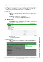
5. Using the Conext Gateway, set the First (LEADER) Inverter Device Number:
a. Go to the inverter’s Configurationpage and enable Advanced View.
b. Under Device Instance set Device Numberto 1.
c. Click Apply.
6. Switch INV2 DISCONNECT (DC disconnect switch) to the ON position.
7. Check inverter display for startup self-test during which LEDs will flash momentarily. Once
self-test is complete, the inverter will display Stb. If the inverter has been pre-configured, it
may go straight into normal operating mode or display F66 warning.
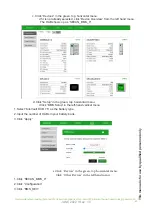
8. Using the Conext Gateway, set the Second (Slave) Inverter Device Number and Inverter
Mode:
a. Select the new inverter XW6848, instance in the device page.
b. Go to the inverter’s Configuration page and enable Advanced View.
c. Under Device Instance set Device Number to 2(or the next unused number).
d. Click Apply. The inverter will now appear as instance 2 in the device list.
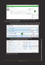
e. Under Multi-unit Configuration, set Inverter Mode to Split Phase Slave.
f. Click Apply.
9. Check for events. If events exist, correct and restart Functional Test.
10. If a third inverter is installed, repeat steps to configure it as a Follower.
11. Using the Conext Gateway, enable the system by going to the Devices page, and next to
System Operating State, click Operating.
12. Confirm the LEADER inverter displays 0 00 and the Followers displays “---” on their front
panels. (We do not recommend using Search on multi-unit systems. The individual displays
may display 0 until AC load breakers are closed. Depending on AC voltage differential, multi-
unit systems may require calibration to reduce “phantom load” effect.)
13. Check for events. If events exist, correct, and then restart Functional Test.
14. Check voltage at AC LOAD terminals of the LEADER inverter.
15. Switch the AC Load breakers ON
20. Basic Functional Test - Multiple Inverters
The following steps will complete a basic functional test of multiple Conext XW Pros. If any
test fails, please refer to the Troubleshooting section in the Owner's Guide for assistance.
To perform a functional test on multiple inverters:
JUNE 2022 / Rev: 1.0
For information about operating the Conext XW+ Pro Inverter/Charger, see the Conext XW Pro Inverter/Charger Owner’s Guide (975-0240-01-01).
68
Содержание HAB 7.5
Страница 1: ...INSTALLATION INTEGRATION GUIDE KiloVault HAB SCHNEIDER XW PRO UL9540 Base Kit JUNE 2022 Rev 1 0 ...
Страница 19: ...This manual is for use by qualified personnel only JUNE 2022 Rev 1 0 2022 17 ...
Страница 73: ...JUNE 2022 Rev 1 0 This manual is for use by qualified personnel only 71 ...

