This manual
is f
or
use b
y qualified personnel
onl
y
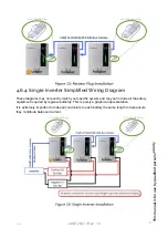
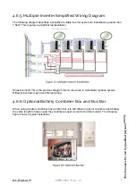
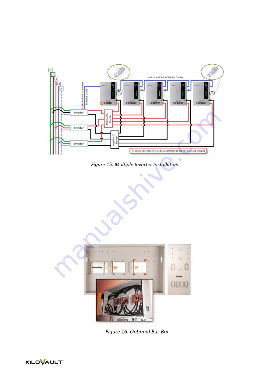
4.6.5. Multiple Inverter Simplified Wiring Diagram
The following diagram describes a simplified multiple inverter system for installations greater than
7.5kW. This is purely a graphical representation.
Wires G/L3/L2/L1/N in the previous diagram refer to the wires in a standard 3-phase system.
Different inverters may have different wiring.
4.6.6. Optional Battery Combiner Box and Bus Bar
When using a battery combiner box and bus bar, it is still critical to get all circuits to each battery
the same length to help ensure they contribute equal current to the total current. The following
figure shows a typical installation.
JUNE 2022 / Rev: 1.0
120
Ω ResistorPlug
28
Содержание HAB 7.5
Страница 1: ...INSTALLATION INTEGRATION GUIDE KiloVault HAB SCHNEIDER XW PRO UL9540 Base Kit JUNE 2022 Rev 1 0 ...
Страница 19: ...This manual is for use by qualified personnel only JUNE 2022 Rev 1 0 2022 17 ...
Страница 73: ...JUNE 2022 Rev 1 0 This manual is for use by qualified personnel only 71 ...

