


18
Assemble units as described herein only. To do otherwise
may result in instability. All screws, nuts and bolts must be
tightened securely and must be checked periodically after
assembly. Failure to assemble properly, or to secure parts
may result in assembly failure and personal injury.
Monitor Arms - Height and Torque Adjustments
Assembly Instructions
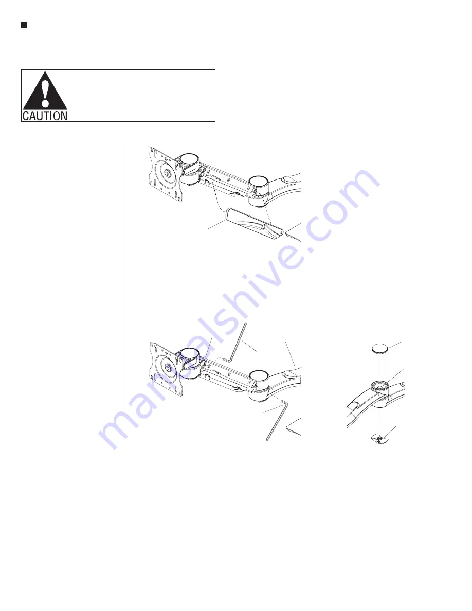
Adjusting the Height-Adjustable
Segment
1. Remove the plastic shroud on
the side of the height-adjustable
segment (Figure 1).
2. With the monitor mounted to the
arm, move the monitor through the
height range; Ensure the arm will
hold the monitor in the position you
placed it (Figure 2).
3. If the monitor lowers or rebounds
upward, adjust the tension screws
at the front and back of the arm
segment as shown using the
3
/
16
”
Allen key. Repeat steps until the
monitor is counterbalanced
(Figure 2).
Adjusting the Torque
1. Remove joint cap from the top of
the joint using a small flat head
screwdriver (Figure 3).
2. Unscrew the cable manager from the
underside of the joint
(Figure 3).
3. Holding the joint bolt in the top of
the joint with a
9
/
16
” socket, use a
second
9
/
16
” socket on the nut in
the bottom of the joint to adjust the
torque setting (Figure 3).
4. Replace cap and reassemble cable
manager.
Final Wiring Connections
1. Make final wiring connections to
appropriate monitor locations after
all components are installed.
Figure 1 - Adjust the Height-Adjusting Segment
plastic
shroud
Figure 2 - Adjust the Height-Adjusting Segment
3
/ ”
16
Allen key
3
/ ”
16
Allen key
front arm
segment
back arm
segment
joint
cap
cable
manager
Figure 3 - Adjust the Torque
joint
bolt
Содержание CFS01
Страница 19: ...19 Monitor Arms Assembly Instructions...


