16
Assemble units as described herein only. To do otherwise
may result in instability. All screws, nuts and bolts must be
tightened securely and must be checked periodically after
assembly. Failure to assemble properly, or to secure parts
may result in assembly failure and personal injury.
Monitor Arms - Triple Screen Monitor Arm - Model CFS07
Assembly Instructions
Triple Screen Monitor Arm
Assembly - Model CFS07 (cont.)
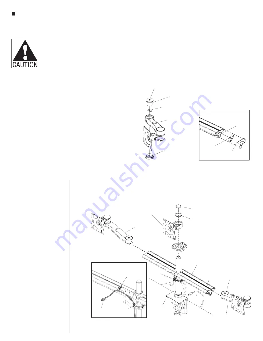
5. To prepare extension arm
assemblies for installation to the
beam, first screw a spacer onto the
threaded end of the set screw on
the underside of each bushing cap
(Figure 3).
6. Insert arm joint bushing into the
underside opening on the extension
arm assembly. Then install a
bushing cap with spacer into the
top openings (Figure 3).
7. Using the spacers located on the
underside of the bushing caps,
slide extension arm assembly
into the “T” slots on top of beam
assembly. Tighten set screw on
top of the bushing cap to secure
monitor assembly in place
(Figure 4).
8. Slide the support ring down the
pole to the desired height of the
monitor screen. Twist the knob on
the support ring to secure in place
(Figure 4).
9. Place monitor mount assembly
down the pole on top of the support
ring (Figure 4).
bushing
cap
spacer
Figure 3
extension arm
assembly
arm joint
bushing
(beam)
set
screw
beam assembly
bushing cap
with spacer
extension arm
assembly
Figure 4
pole
assembly
support
ring
monitor
cable
support
ring tab
“T” slot
on top of
beam
“T” slot
on backside
of beam
monitor
cable
support
ring tab
Detail B
monitor mount
assembly
extension arm
assembly
pole cap
trim ring
10. Mount the trim ring on top of the
monitor mount assembly followed
by re-installing the pole cap on top
of the pole assembly (Figure 4).
11. Slide beam cable managers into
the “T” slots on the backside of the
beam assembly as illustrated. Then
install beam end cap on to each end
of the beam assembly (Detail A).
12. Insert monitor cables through
support ring tabs. Next, feed
monitor cables through beam cable
managers installed on the backside
of the beam assembly (Figure 4 &
Detail B).
13. To properly install monitor
screen to the faceplate of the
monitor mount assembly,
reference “Mounting the Monitor”
instructions on page 17.
Detail A
beam
cable
manager
beam
end cap
“T” slot
on backside
of beam
Содержание CFS01
Страница 19: ...19 Monitor Arms Assembly Instructions...


