281
16.35.3.2
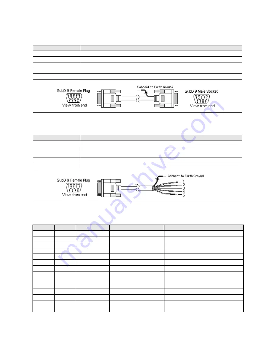
Wiring for cable connections using
OMRON CJ1W-SCU41
communication module
with RS-422
Host Link D-Sub 9 Female Plug ports.
KEP Part#: (Not Available) (D-Sub 9 Female Plug to D-Sub 9 Male Socket Cable)
HMI PLC[RS-485]
Connect to OMRON CJ1W-SCU41 RS-422 Host Link port
1 RXD-
Æ
1 SDA
2 RXD+
Æ
2 SDB
3 TXD-
Æ
6 RDA
4 TXD+
Æ
8 RDB
7
Æ
Shield
Æ
Earth Ground
16.35.3.3
Wiring for cable connections using
OMRON CJ1W-CJ1W-C1F11
communication module
with RS-
422 Host Link screw terminal ports.
KEP Part#: (Not Available) (D-Sub 9 Female Plug to flying leads)
HMI PLC[RS-485]
Connect to OMRON CJ1W-CJ1W-C1F11 RS-422 Host Link port
1 RXD-
Æ
3 SDA-
2 RXD+
Æ
4 SDB+
3 TXD-
Æ
1 RDA-
4 TXD+
Æ
2 RDB+
5 GND
Æ
7
Æ
Shield
Æ
Earth Ground
Note:
Graphic representation may not reflect the actual appearance of the finished cable.
16.35.4 Device address
Bit/Word
Type
Address Format
Range
Notes
B
CIO
ddddbb
dddd: 0~6143 bb: 00~15
Always use 2 digits for bit designation
B
HR
dddbb
ddd: 0~511 bb: 00~15
Always use 2 digits for bit designation
B
AR
dddbb
ddd: 0~959 bb: 00~15
Always use 2 digits for bit designation
B
LR
dddbb
ddd: 0~199 bb: 00~15
Always use 2 digits for bit designation
B
T(Status) dddd
dddd: 0~2047
Timer Completion coil status
B
C(Status) dddd
dddd: 0~2047
Counter Completion coil status
W
T(Value) dddd
dddd: 0~2047
Timer actual time value
W
C(Value) ddd
ddd: 0~2047
Counter actual count
W
DM
dddd
dddd: 0~6143
Data Memory
W
EM
dddd
dddd: 0~9999
Extended Memory
W
CIOW
dddd
dddd: 0~9999
Channel I/O as words
W
HRW
dddd
ddd: 0~511
Holding Relay as words
W
ARW
dddd
ddd: 0~959
Auxiliary Relay as words
W
LRW
dddd
ddd: 0~199
LR as words
Note:
The Controller’s memory range may vary within the range supported by the driver. Use appropriate addresses.
Содержание MMI-1500
Страница 2: ...ii...


