142
2. Have the PLC check a register for a password value and use a PLC bit to activate the Numeric Input for added security.
3. Fill in
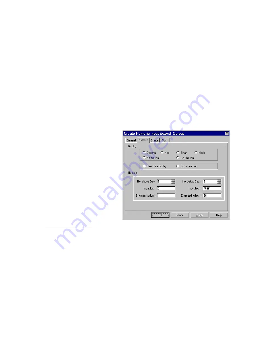
Numeric
Tab items:
Display: Manipulates data so it is displayed in a useful format. See
13.8.1 Numeric Display Format
section below.
4. Go to
Shape
Tab: Select Shape or Bitmap to be used as a background button. The button is used to identify the part as
an input part as opposed to just a regular data display. The button changes state when pressed.
Note:
Refer to Bit Lamp procedure for more details on filling out the Shape tab.
5. Go to
Font
Tab: Fill in attributes for the displayed digits. See
13.8.2 Font Alignment
below for details.
6. Click
OK
to place the Numeric Input part on the window. Position the Numeric Input part and resize it if necessary. Adjust
the number position just as you would any other label.
Note:
Refer to Section 2: Software Reference Guide for details about completing each tab item
Note:
Reserved Local Bit for Keypad.
When the user activates a Numeric or ASCII Input object, the HMI turns internal bits LB9060~LB9069
ON
. After user input
and entry, the HMI checks the input data, if the data is valid then LB9060~LB9069 are turned
OFF
otherwise the input
remains active waiting for valid entry. This is used for controlling popup keypads, see below.
13.8.1 Numeric Display Format
Decimal
:
For
Raw data Display
, the reading value is displayed in its
original value as a decimal number in the range –32768 to
32767.
For
Do conversion,
the reading value is converted to
engineering units before display.
Fill in the
Numeric
portion of the tab.
Specify number above decimal point and number below
decimal point.
Scaling is performed as follows:
Display value = (reading value – Input Low) * (Engineering High – Engineering Low)
(Input High – Input Low)
Note:
PLCs can only accept integer values. This affects how the HMI enters and displays scaled values. It is especially
evident when scaling from a smaller value to a larger value. For example: Scaling a 0-10 value to a 0-100 value only yields
multiples of 10. A value of 25 can never be displayed. Entering a value of 29 returns a value of 20. The HMI does not
“round”. It can only truncate to the next lower value.
Note:
The decimal point for
Do Conversion
shows the actual decimal portion from the scaling formula. Data entered in the
Decimal portion is used for converting data back to the PLC. Make sure keypads used for data entry contain a Decimal point
for these cases.
The Decimal point for
Raw data display
is for appearance only and does not indicate that scaling has been done. For
example: The No. below Dec. is set to 2. The value from the PLC is 104. The value is displayed as 1.04. Entering a value of
1.55 sends 155 to the PLC.
Note:
Be sure to set Input limits to the values that is sent to the PLC not displayed values. For example: Using the example
in the note above, Input limits might be Input low = 0; Input high = 200; (not Input low = 0 Input high = 2).
Содержание MMI-1500
Страница 2: ...ii...


