Connection of the control | 4
ma_dr_f6-cu-p-inst-20182705_en
17
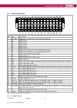
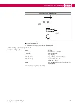
4.2 Terminal strip X2A
1
2
3
4
5
6
7
8
9
10
11
12
13
14
15
16
17
18
19
20
21
22
23
24
25
26
27
28
PIN
Name
Description
1
DI1 / AN3
Digital input 1 / analog input 3 (switchable via software)
2
DI2
Digital input 2
3
DI3
Digital input 3
4
DI4
Digital input 4
5
DI5
Digital input 5
6
DI6
Digital input 6
7
DI7
Digital input 7 (fast input => see programming manual)
8
DI8
Digital input 8 (fast input => see programming manual)
9
0V
Reference potential for digital output
10
DO1
Digital output 1
11
0V
Reference potential for digital output
12
DO2
Digital output 2
13
RLB
Relay output / NC contact (no function at relais variant „relay with positively driven contacts“)
14
RLA
Relay output / NO contact
15
RLC
Relay output/ switching contact
16
24Vout
DC voltage output 24V (max. 100 mA together with terminal 26) for control the inputs (SELV).
17
AN1-
non-isolated difference input 1
18
AN1+
Non-isolated difference input 1
19
AN2-
non-isolated difference input 2
20
AN2+
Non-isolated difference input 2
21
0V
Reference potential for analog inputs and outputs
22
ANOUT
Analog output DC 0…10 V
23
CAN low
CAN bus ISO High Speed according to ISO/DIN 11896 => fieldbus interfaces
24
CAN high
CAN bus ISO High Speed according to ISO/DIN 11896 => fieldbus interfaces
25
CAN GND
CAN ground isolated => fieldbus interfaces
26
24VoutCtrl
DC voltage output 24V for supply the control board (SELV). Attention, do not link with voltag
supplies of other devices!
27
0V
Reference potential for P24Vin at external supply
28
P24Vin
Voltage output DC 24V for supply the control board and the brake
Tab. 9:
Assignment of the terminal strip X2A
4.2.1 Digital Inputs
Specification
Number
8


