7 | Fieldbus interfaces
KEB Automation KG
32
ma_dr_f6-cu-p-inst-20182705_en
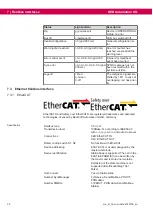
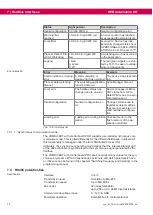
Status
Light pattern
Description
Invalid configuration r-0 (grid 200 ms)
General configuration error.
Warning limit
reached
r-0-0-0-0-0 (grid 200 ms)
An error counter has reached
or exceeded the warning level.
Local Error
r-0-0-0-0-0 (grid 200 ms)
Local error; Device has inde-
pendently changed status from
OPERTIONAL to SAFE-OPER-
ATIONAL. Error bit is set to "1".
Process Data or Eth-
erCAT Watchdog
r-0-r-0-0-0-0-0 (grid 200
ms)
A watchdog error has occurred
in the application.
Legend
r: Red
g: Green
0: off
The red/green signals are shif-
ted by 180°. In case of overlap-
ping, red has priority.
Error status list
Error
Meaning
Example
Communication or device
error
A communication or
device error has occurred.
The device stops respond-
ing
Process data watchdog
timeout
The watchdog application
reports a timeout.
Sync-Manager timeout
Local error
The fieldbus status has
changed due to an error.
Device changes its Ether-
CAT status from OP to
SafeOPError due to a syn-
chronisation error.
Invalid configuration
General configuration er-
ror
Change of status due to
register or object settings
that are not possible or in-
valid hardware configura-
tion.
Loading error
Loading error during initial-
isation
Checksum error in the
flash memory of the ap-
plication controller.
Tab. 15:
Error status list
7.3.1.1 Synchronous communication mode
The COMBIVERT with control board PRO supports a so-called synchronous com-
munication mode. This is titled differently for the different fieldbuses. In EtherCAT,
this functionality is managed under the term Distributed Clocks (DC).
Ultimately, the synchronous operating mode means that the internal interrupt grid
of the drive controller is synchronised to the synchronous signal generated by the
fieldbus.
The COMBIVERT with control board PRO does not support any values for the syn-
chronous cycle time. Which dependencies exist here and which parameters have
an influence can be found in the chapters "Switching frequency and derating" in the
programming manual.
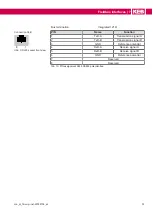
7.4 RS485 potential-free
Specification
Interface
Transmission level
According to EIA-485
Transmission speed
Up to 500 kBit/s
Bus nodes
32 nodes (standard)
up to 256 at min. 96 kΩ input resistance
Common-mode voltage range
0…12 V to GND
Potential separation
Potential-free to control potential.

