Fieldbus interfaces | 7
ma_dr_f6-cu-p-inst-20182705_en
31
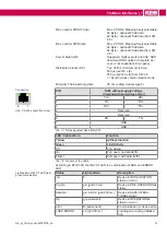
Max. number PDOUT data
Max. 2 PDOs; Mapping freely selectable.
32 Byte + optional FSoE data.
64 Byte + optional FSoE data (from SW
2.8).
Max. number PDIN data
Max. 2 PDOs; Mapping freely selectable.
32 Byte + optional FSoE data.
64 Byte + optional FSoE data (from SW
2.8).
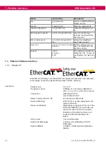
Acyclic data traffic:
Supported mailbox protocols CoE; SDO
download; SDO upload (Complete Ac-
cess is not supported); Emergency
Distributed Clocks (DC)
Yes, 32 Bit; minimum cycle time:
500 µs (is22=8 x tp)
250 µs (is22=4 x tp) from SW 2.8
=> Synchronous communication mode
Minimum FSoE watchdog time
35 ms (safety module type 5)
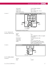
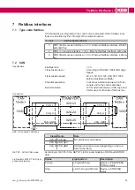
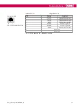
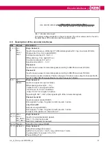
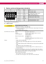
Connection
1
8
Abb. 4:
RJ45 socket front view
PIN
RJ45 without supply voltage
(Viewing with Auto-Cross Over)
1
TX+
RX+
2
TX-
RX-
3
RX+
TX+
4
Reserved
5
Reserved
6
RX-
TX-
7
GND
8
GND
Tab. 13:
PIN assignment RJ45 EtherCAT
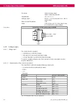
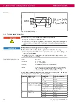
LED / light pattern
Function
Yellow
without function
Green
Link/Activity
Off
Port closed
On
Port open; no data traffic
Flicker
Port open; with data traffic
Tab. 14:
Function of the LEDs
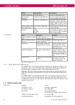
According to ETG1300, the NET ST LED is a combination of RUN and ERROR
LED.
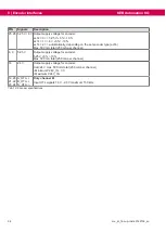
Light pattern NET ST LED (red/
green combination)
Status
Light pattern
Description
init
0
Device in INITIALISATION
status; no error
Pre-Op
g-0 (grid 50 ms)
Device in PRE-OPERATIONAL
status
Safe-Op
g-0-0-0-0-0 (grid 200 ms)
Device in SAFE-OPERA-
TIONAL status
Op
g (permanent)
Device in OPERATIONAL
status; no error
error
R (permanent)
Communication or device error.
LOAD ERROR
r-0 (grid 50 ms)
Loading error during initialisa-
tion

