background image

2 Unit description

6

FOCUS

Exposure time control

Содержание FOCUS 215720

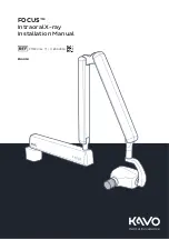
Страница 1: ...FOCUS Intraoral X ray Installation Manual 215720 rev 11 0 805 4950 ENGLISH Dental Excellence FOCUS...

Страница 2: ......

Страница 3: ...s the documentation may not be copied photocopied reproduced translated or reduced to any electronic medium or machine readable form in whole or part without the prior written permission of Instrument...

Страница 4: ......

Страница 5: ...rm 20 4 6 Leveling the horizontal arm 22 4 7 Adjusting the scissors arm 23 4 8 Installing the remote controller 25 4 8 1 Mounting the remote control to the wall 25 4 8 2 Mounting the control panel to...

Страница 6: ...ii...

Страница 7: ...unit please refer to the User Manual Device Installation Manual and User Manual are shipped with each unit These manuals and future updates will be available upon request from the manufacturer It is s...

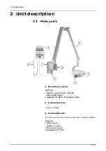
Страница 8: ...Mounting system Options Narrow wall mount default Wide wall mount Adapter for KaVo treatment units 2 Connection box Mains wiring 3 Horizontal arm Includes an electronics module and internal cables Op...

Страница 9: ...cone full metal rectangular 7 Remote control panel Includes a 10m cable and exposure button on the control panel 8 Optional Remote exposure switch Use original FOCUS accessory remote exposure switch r...

Страница 10: ...SD 229 mm 9 60 mm Short cone rectangular SSD 229 mm 9 35x45 mm Long cone round SSD 305 mm 12 60 mm Long cone rectangular SSD 305 mm 12 35x45 mm Short cone full metal rectangular SSD 229 mm 9 35x45 mm...

Страница 11: ...uspid Maxillary incisors Bitewing Mandibular molar Mandibular cuspid Mandibular incisors Occlusal Exposure button X ray source assembly emitting Ready for exposure Patient Size Selection Digital mode...

Страница 12: ...2 Unit description 6 FOCUS Exposure time control...

Страница 13: ...atment unit is allowed only when the manufacturer of the treatment unit has tested the mechanical stability and allow the integration For KaVo treatment unit integration refer the compatibility table...

Страница 14: ...stem is measured from the tip of the cone with the arm fully extended and the cone pointing back towards the pivot of the wall plate This measurement method accommodates the normal positioning of the...

Страница 15: ...equired during the installation Metric Allen wrench set Electric drill drill bits 8 mm 10 mm or equal Mounting hardware for wall bracket Pencil or drawing ink Spirit Level Hammer Anchor driver concret...

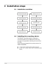
Страница 16: ...th four 4 bolts There are several supported mounting devices for FOCUS installation a single stud wall mounting plate narrow a 16 inch center stud wall mounting plate wide EKVTU UIF GSJDUJPO CSBLFT 4F...

Страница 17: ...material of the wall or a mounting surface and choose the mounting system according to the following examples Mount the unit so that the lower edge of the mounting plate is approximately 47 inches 110...

Страница 18: ...te If the unit is mounted to a wall with 16 inch center studs specify the site of the unit and fasten the mounting plate firmly to the wall Level the mounting plate NOTICE Any property damage or perso...

Страница 19: ...tment unit The adapter kits are available from KaVo as treatment unit accessory An integration kit with hardware and mains cable is available when mounting FOCUS on the KaVo treatment unit adapter Onl...

Страница 20: ...ntrol into the bottom of the treatment unit s pole and up through the KaVo unit mount adapter leaving approx 15 cm 6 inches of the cables sticking out through the adapter To make the routing upwards t...

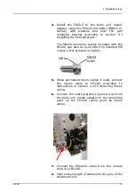
Страница 21: ...can also be used after the included M8 nuts are first screwed on tightly 5 When permanent mains option is used connect the mains cable to FOCUS according to instructions in section 4 10 Connecting ma...

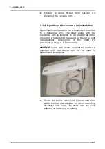
Страница 22: ...ntal arm is installed to an adapter or other mounting structure not managed by the X ray unit manufacturer Dimensions of the shaft are presented in chapter 6 Dimensions NOTICE Some wall mount installa...

Страница 23: ...the installation according to chapter 4 4 Installing the scissors arm 4 3 Installing the horizontal arm Lift the horizontal arm to its place and attach the nuts as shown in the image below Note that...

Страница 24: ...e wall end of the horizontal arm first remove the wall mounting bracket cover Turn the horizontal arm pointing to the left and unscrew the screw of the horizontal arm cover Loosen the screws b on the...

Страница 25: ...the scissors arm can open with force Route the cables of the scissors arm through the hole bearing on the horizontal arm Fit the shaft of the scissors arm into the hole of the horizontal arm Assure t...

Страница 26: ...5 1 Outer end of the horizontal arm 1 Hold the adjustable brake and insert the shorter screw a slightly so that the adjustable brake stays in position 2 Insert two longer screws b into the adjustable...

Страница 27: ...4 Installation steps FOCUS 21 CAUTION Secure the cables with the cable tie 4 Attach the horizontal arm cover and fasten it with the screw at the bottom of the cover...

Страница 28: ...instructions do not apply to OpenMount installation Adjust the horizontal arm according to the instructions provided with the mounting adapter 1 Loosen the nuts on both sides of the horizontal arm br...

Страница 29: ...ssure that the horizontal arm stays in position 6 After adjusting the horizontal arm cut off the safety strap to release the scissors arm 4 7 Adjusting the scissors arm Although the factory adjustment...

Страница 30: ...cissors arm with a screwdriver to adjust the tension of the springs To increase the tension turn the nut clockwise To decrease the tension turn the nut counter clockwise NOTICE Use a 3 mm 1 8 Allen ke...

Страница 31: ...ds the tubehead 4 8 Installing the remote controller 4 8 1 Mounting the remote control to the wall 1 Take the remote controller assembly and use it as a template to determine the preferred mounting lo...

Страница 32: ...The used screws shall be 4mm pan head screws 4 Hang the remote control on the wall by the mounting screws 4 8 2 Mounting the control panel to a treatment unit 1 Remove the plastic cover of the remote...

Страница 33: ...arp or hard tools when you remove the circuit board NOTICE Take special care when you handle the circuit board The circuit board can be easily damaged by excessive use of power 3 Remove the Ethernet c...

Страница 34: ...tton by opening the nut from the strain relief 6 Attach the control panel frame to the optional electronics mounting plate of the treatment unit adapter kit 7 Install the included short Ethernet cable...

Страница 35: ...d to disable the primary exposure button on the control panel and enable only the external exposure button 11 Carefully connect the Ethernet cable to connector X21 and the remote exposure button cable...

Страница 36: ...installation the following instructions may be used In this instruction the terminal strip X61 at the unit connection box board is used instead of the RJ 45 terminal connector X62 or X63 NOTICE Use on...

Страница 37: ...ote control panel to the unit X ray unit 3 Remove cable tubing carefully about 2 50mm 4 Strip the wires about 1 3 8mm 5 Attach stripped wires to terminal strip X61 as shown in the table below In case...

Страница 38: ...1 white green 1 CS 2 green 2 GND 3 white orange 3 CLK 4 blue 4 DOUT 5 white blue 5 BEEP 6 orange 6 DIN 7 white brown 7 EXP 8 brown 8 PWR RJ45 control panel board X21 connection box board terminal stri...

Страница 39: ...l from Connection Box is connected to ground Door is closed OFF open Door signal from Connection Box is connected to door switch Causes Error H3 2 unused 3 ON closed Enables exposure signal for Remote...

Страница 40: ...an be wired directly to the CPU board in the generator module if needed NOTICE If a door switch is not used with the OpenMount configuration connect a jumper between the pins 9 and 10 of connector X31...

Страница 41: ...4 Installation steps FOCUS 35 4 9 1 Example 1 1 remote with exposure button disabled exposure hand wall switch from Connection Box one door switch from Connection Box and one door switch from remote...

Страница 42: ...4 Installation steps 36 FOCUS 4 9 2 Example 2 1 remote with 2 exposure hand wall switches connected in series remote exposure button disabled...

Страница 43: ...4 Installation steps FOCUS 37 4 9 3 Example 3 2 remotes using a selector switch exposure hand wall switch from each remote...

Страница 44: ...4 Installation steps 38 FOCUS 4 9 4 Example 4 Remote control and external exposure button in series...

Страница 45: ...how it has been installed The non permanently installed unit is connected with power supply cord and mains plug when electric current L passes through both main fuses F2 and F3 in the wall mounting b...

Страница 46: ...115 V 15A Type SJT min 14AWG max 3 m 9 8 ft Complies with UL817 and CSA C22 2 NO 21 WARNING Only a qualified technician is permitted to carry out these connections WARNING Before connecting to the mai...

Страница 47: ...permanently installed unit 3 Plug the cable F32 between the mains switch connector at the back on the left and fuse F3 4 Plug the blue cord of the cable F33 between mains switch connector slot which i...

Страница 48: ...the mains switch connector Cable markings are found on the cables NOTICE Do not mix the cable F3 and the fuse F3 6 The power supply cable is connected to the terminal block X91 as shown in the image...

Страница 49: ...switch connector and from the terminal block X91 Cable markings are found on the cables Circuit diagram 2 Cable connections in a non permanently installed unit 2 Plug the blue cord from the cable F4...

Страница 50: ...same side as the black cord in the cable F52 Cable markings are found on the cables NOTICE Do not mix the cable F3 and the fuse F3 5 Twist the part a to the wall mounting bracket Tighten the part a a...

Страница 51: ...cables and plugs 4 10 4 Permanent installation to 115 VAC NOTICE For permanent installation a separate lockable mains switch not supplied is required to be installed The power supply cable is connect...

Страница 52: ...a screwdriver The fuse with the base will come out Remove the fuse from the base and replace it with the new one Repeat this with each fuse Fasten the fuses by pushing the base up and twisting it clo...

Страница 53: ...ce mounted remove a piece from the mounting bracket cover in order to allow the remote control cable to fit in If the unit is supplied with two remote controls do the same on the opposite side Fasten...

Страница 54: ...nd down to check that the movements are smooth to both directions and that the tube head stays in position 4 Check Protective Earth PE grounding resistance according to the IEC 62353 Medical electrica...

Страница 55: ...6 Dimensions FOCUS 49 6 Dimensions Wide wall mount plate measures in mm...

Страница 56: ...6 Dimensions 50 FOCUS Narrow wall mount plate measures in mm...

Страница 57: ...6 Dimensions FOCUS 51 Remote control frame measures in mm...

Страница 58: ...6 Dimensions 52 FOCUS Wall mount installation dimensions...

Страница 59: ...6 Dimensions FOCUS 53...

Страница 60: ...6 Dimensions 54 FOCUS...

Страница 61: ...6 Dimensions FOCUS 55...

Страница 62: ...6 Dimensions 56 FOCUS OpenMount installation dimensions...

Страница 63: ...oup Oy representative for the most current information Copyright by PaloDEx Group Oy All rights reserved Headquarters PaloDEx Group Oy Nahkelantie 160 FI 04300 Tuusula FINLAND Tel 358 10 270 2000 http...

Отзывы: