Kathrein UFS 924 Скачать руководство пользователя страница 2

2

Mains power cable

Make  sure that the mains cable 

(power supply cable) is not damaged. 

Units  with a damaged mains cable 

must be disconnected from the mains 

(unplug it at the socket) and repaired 

by  an electrical specialist before 

setup. Only use the power supply unit 

supplied (if available)!

Mortal danger due to electric shock!

Danger!

Cleaning

Disconnect  the mains plug before 

cleaning the unit. Use a dry cloth for 

cleaning  and only clean the outer 

surface. Never open the casing of the 

unit.

Touching the parts inside the unit 
carries a risk of death due to electric 
shock!

Playing children

Make sure that children do not push 

any objects into the ventilation slots.

Mortal danger due to electric shock!

Earthing

The antenna system must be earthed 

as  specif ed  or equipotentially 

bonded.

EN  60728/11  and any national 

regulations must be complied with. 

Risk of voltage surges due to lightning 
strikes!

Power supply voltage

Only operate the unit at the speci f ed 

mains voltage (indicated on the rear of 

the unit or on the external power pack). 

The unit may only be connected to the 

mains and turned on once it has been 

connected to the antenna and to the 

TV set or the cable network and PC.

If the mains voltage is too high, there 
is a risk of fi re!

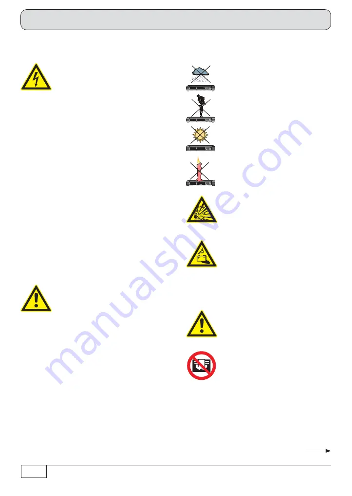
Moisture, direct sunlight, heat, 
naked fl ames

Protect  the unit against moisture, 

dripping  and splashed water (do not 

place any f lled objects such as vases 

on top of the unit). Do not place the 

unit close to a heater or expose it to 

direct  sunlight and do not operate it 

in damp locations. Only use the unit 

in a moderate climate, not in tropical 

conditions! Do not place naked f ames 

such as candles on top of the unit! 

There is a risk of fi re!

Ventilation

The  heat generated in this unit is 

adequately  dissipated. However , 

the  unit should never be installed 

in  a cupboard or on shelves with 

inadequate 

ventilation. Never 

cover  the cooling slots on the 

unit  (e.g. with other equipment, 

magazines,  tablecloths, clothing or 

curtains)!

Batteries

If your unit was supplied with batteries 

(e.g. for the remote control), take care 

that  the batteries are not exposed 

to  excessively high temperatures, 

direct  sunlight or  f re.  Replace the 

batteries  only with types that are 

identical  or equivalent, otherwise 

the  batteries or the remote control 

may  be damaged.  Also  comply with 

the  safety instructions stated on 

the batteries:

There is a risk of explosions!

Warning!

Warning!

Warning!

These two pages contain important information about the operation, installation location and connection of 
the unit. Read these instructions carefully before setting up the unit.

Safety instructions - important notes

Do not 

cover

Содержание UFS 924

Страница 1: ...Network Internet access 44 Common Interface CI Smartcard reader 46 Inserting the Smartcard and the CI Module 46 Troubleshooting 47 Service 48 Technical Appendix 49 Advanced connection example 49 Tech...

Страница 2: ...o high there is a risk of fire Moisture direct sunlight heat naked flames Protect the unit against moisture dripping and splashed water do not place any f lled objects such as vases on top of the unit...

Страница 3: ...at base Repair Ensure that any repairs to your unit are carried out by qualif ed personnel Opening the unit and attempting to repair it yourself will void all warranty claims Improper work on the unit...

Страница 4: ...anged or new data that are broadcast will be saved by the receiver As soon as the receiver is in the standby mode it can be disconnected from the mains at any time The information in these operating i...

Страница 5: ...77 HDMI cable Power cable 2 batteries AAA 1 5 V Operating Instructions Part 1 2 and 3 Safety instructions multi lingual The accessories supplied may differ in appearance from those illustrated Loop th...

Страница 6: ...6 Front rear view of the receiver front flap open Connection and setup 24 14 13 12 23 20 19 15 26 21 11 22 18 25 17 16 5 6 8 9 3 7 4 1 2 10...

Страница 7: ...SPDIF Sony Philips Digital Interface Format for Dolby Digital AC 3 audio 21 Electrical digital data stream output SPDIF Sony Philips Digital Interface Format for Dolby Digital AC 3 audio 22 Video outp...

Страница 8: ...eries supplied into the remote control Ensure correct polarity of the batteries the and markings are indicated inside the battery compartment Slide the cover back onto the housing until it locks in pl...

Страница 9: ...the satellite reception system Use coaxial cable with an F standard connector see illustration on right HDMI Scart TV Conventional DiSEqC system Connect the satellite receiver HDMI or alternatively T...

Страница 10: ...xample in the technical appendix SPDIF Sony Philips Digital Interface Format digital output for Dolby Digital AC 3 audio Connect the satellite receiver VCR AUX Scart socket to the video recorder DVR u...

Страница 11: ...connected to a single cable system The receiver tuner inputs are factory preset in the installation menu to work with two separate Sat antenna connections In cases where only one antenna connection is...

Страница 12: ...f rm the changed values setting call up the submenus Select change individual menu parameters navigation Cancel input go back First switch your TV set on and select the AV HDMI input you have used to...

Страница 13: ...pe of screen display depending on your setting for the aspect ratio TV aspect ratio 4 3 Pan Scan or Letterbox TV aspect ratio 16 9 Always 16 9 or automatic HDMI YPbPr SCART or HDMI YPbPr Resolution He...

Страница 14: ...ou can select the type of screen display mode for 4 3 broadcasts on a 16 9 TV set Either Normal Pillarbox Stretched full screen or Zoom in Pan Scan Audio Format via HDMI Here you can select the type o...

Страница 15: ...ceiver in this section only one change selection is necessary in the rest of the first installation If you are not familiar with the details of your reception system note the following In many cases t...

Страница 16: ...urrently selected setting is shown graphically in the connection example at the top left of the screen Either Separated The second tuner input of the receiver LNB2 IN receives its own signal input i e...

Страница 17: ...vailable for Tuner 2 connection type Separated Tuner 2 signal configuration Same with Tuner 1 All settings are made on Tuner 1 The settings for the second tuner are automatically taken from the f rst...

Страница 18: ...he desired satellite using the buttons Alternatively you can press the button to view a list of all stored satellites then select the required satellites from this list LNB Type If your reception syst...

Страница 19: ...ne satellite four max for Tuner 1 you can now de f ne the settings as described above for the f rst satellite for the second satellite and then for the third and fourth satellites if selected When you...

Страница 20: ...the button The following on screen display appears Press the green button Satellite Select the desired satellite using the buttons Alternatively you can press the button to view a list of all stored...

Страница 21: ...your reception system Refer to the documentation for your reception system or seek assistance from a specialist engineer Off DiSEqC command is not repeated 1 DiSEqC command is repeated once 2 DiSEqC c...

Страница 22: ...ou should now def ne the settings for the second tuner in the same way as you did for the f rst tuner Once you have completed the settings for both tuners and the satellites assigned to them the recei...

Страница 23: ...urntable has only a restricted range in which it may turn before striking an obstruction such as a wall or tree Press the button The following on screen display appears The following buttons allow you...

Страница 24: ...e borders You can now set new values for the limits Once you have set all the borders press the button Here select up to 64 satellites to be included in the signal on Tuner 1 Select the satellite you...

Страница 25: ...ned LNB Frequencies MHz Enter the LNB frequencies Low High Limit using the number pad Now use the button to save the new values Test Transponder Select the T est Transponder f eld Here you can select...

Страница 26: ...or the second satellite and for any other selected satellites When you have completed all settings for the selected satellites press the button When you have completed all settings for Tuner 1 press t...

Страница 27: ...ld In this menu you can set the borders for your turntable This is particularly necessary if the turntable has only a restricted range in which it may turn before striking an obstruction such as a wal...

Страница 28: ...ner 1 Go to the Select Satellites line Press the button The following on screen display appears example Here select up to 64 satellites to be included in the signal on Tuner 1 Select the satellite you...

Страница 29: ...ther your settings are correct using the signal strength bar and signal quality bar If you have selected more than one satellite for Tuner 1 def ne the settings as just described for the f rst satelli...

Страница 30: ...list LNB Type If your reception system does not have a universal LNB use the buttons to select the LNB types that are used in your reception system You can choose from the following LNB types Univers...

Страница 31: ...Select the Test Transponder f eld Here you can select a transponder for checking whether your settings are correct using the signal strength bar and signal quality bar When you have completed all sett...

Страница 32: ...fer to the documentation supplied with your system for the settings for the SCRs frequencies and any PIN assigned to the tuner Here you will find a printed list showing the assignment between the vari...

Страница 33: ...r can then use this transmission frequency unless the PIN is input Select Yes You can now enter a PIN code 0 255 on the next line Tuner 1 PIN Code using the number pad Tuner 1 Select a free available...

Страница 34: ...ing the buttons Alternatively you can press the button to view a list of all stored satellites then select the required satellites from this list LNB Type If your reception system does not have a univ...

Страница 35: ...elected two satellites con f gure the settings as just described for the f rst satellite for the second satellite When you have completed all settings press the green button When you have completed al...

Страница 36: ...atively you can press the button to view a list of all stored satellites then select the required satellites from this list Test Transponder Select the Test Transponder f eld Here you can select a tra...

Страница 37: ...eiver can then use this transmission frequency unless the PIN is input Select Yes You can now enter a PIN code 0 255 on the next line T uner 1 PIN Code using the number pad Tuner 1 Select a free avail...

Страница 38: ...ing the buttons Alternatively you can press the button to view a list of all stored satellites then select the required satellites from this list LNB Type If your reception system does not have a univ...

Страница 39: ...signal strength bar and signal quality bar When you have completed all settings for the selected satellites press the button If you have selected two satellites con f gure the settings as just describ...

Страница 40: ...Austria and Switzerland Channel search Connection and setup Satellite Now use the buttons to choose between the individual satellites you have set up or select the setting All Satellites If All Satel...

Страница 41: ...the same way as the existing transponders When you have completed all settings press the green button The following displays appear at f rst example The receiver independently updates the ASTRA chann...

Страница 42: ...nd time When you have completed the settings press the green button to complete the f rst installation After completing the search you will see the following on screen display example Press the button...

Страница 43: ...te process refer to the section Mainmenu Service Menu Software Update by satellite in the Operating Instructions Part 2 Once the f rst installation has be successfully carried out you may change the c...

Страница 44: ...n be made using the buttons or the numeric keypad An Internet connection is required for the use of the Red Bull MEDIA HOUSE PORTAL These settings should not be defined unless the receiver is linked i...

Страница 45: ...nd press the button to conf rm Def ne the settings for your network as required When you have completed all the settings switch back to the Save f eld and press the button to conf rm Configuration exa...

Страница 46: ...r encryption technology is inserted into the CI module Store your card and PIN code securely when not in use Common Interface CI Smartcard reader Inserting the CI module into the CI The Common Interfa...

Страница 47: ...nt Check the batteries see also Inserting batteries into the remote control in the Operating Instructions Part 1 Receiver or remote control command set may have been unintentionally changed Set infrar...

Страница 48: ...by HbbTV Select a channel transmitter that is provided by HbbTV e g ARD or ZDF Internet connection is not available Check that the cross over network cable is correctly connected clicked home receiver...

Страница 49: ...49 Technical Appendix Advanced connection example HiFi system Network PC Laptop External hard drive Dolby digital system...

Страница 50: ...e and change of picture content Approx 300 hours for SDTV approx 100 for HDTV depending on data rate and change of picture content Power supply Power supply voltage V Hz 230 50 60 Power consumption ma...

Страница 51: ...51 Technical Appendix Sat IF connection examples Overvoltage protection KAZ 11 KAZ 12 Individual reception systems Community antenna network systems 4 x Sat IF Sat IF Sat IF Sat IF...

Страница 52: ...52 Technical Appendix Overvoltage protection KAZ 11 KAZ 12 Community antenna systems 8 x Sat IF Multifeed Community antenna systems 16 x Sat IF Multifeed Sat IF Sat IF Sat IF Sat IF...

Страница 53: ...53 Technical Appendix Overvoltage protection KAZ 11 KAZ 12 Single cable systems Sat IF...

Страница 54: ...54 Technical Appendix Overvoltage protection KAZ 11 KAZ 12 Sat IF Sat IF...

Страница 55: ...z B FRITZ Box TCP IP Adresse automatisch Funkstrecke Technical Appendix DHCP Receiver ON UFS 924 Internet Connection Examples for the Network Function Network cable Radio link PC Laptop TCP IP addres...

Страница 56: ...PC Laptop Netzwerkkabel DHCP Server Router z B FRITZ Box TCP IP Adresse automatisch Funkstrecke DHCP Receiver ON UFS 924 Internet Network cable Radio link PC Laptop TCP IP address automatic DHCP serve...

Страница 57: ...enthalten DHCP Server Router z B FRITZ Box Funkverbindung nur mit UFZ 130 m glich Funkstrecke TCP IP Adresse automatisch Internet Radio link PC Laptop TCP IP address automatic DHCP server router e g...

Страница 58: ...92 168 0 13 TCP IP Adresse 192 168 0 12 TCP IP Adresse 192 168 0 11 TCP IP Adresse 192 168 0 10 Netzwerkkabel Netzwerkkabel Internet Network cable TCP IP address 192 168 0 13 DHCP server router e g FR...

Страница 59: ...P IP Adresse 192 168 0 12 PC Laptop Netzwerkkabel Netzwerkkabel TCP IP Adresse 192 168 0 10 TCP IP Adresse 192 168 0 11 Internet TCP IP address 192 168 0 12 Switch HUB Network cable TCP IP address 192...

Страница 60: ...Appendix DHCP Receiver OFF UFS 924 PC Laptop Gekreuztes Netzwerkkabel IP Adresse 192 168 0 10 IP Adresse 192 168 0 11 Switch HUB Cross over network cable IP address 192 168 0 10 IP address 192 168 0...

Страница 61: ...61 For your notes For your notes...

Страница 62: ...62 For your notes...

Страница 63: ...63 For your notes...

Страница 64: ...nternet www kathrein de KATHREIN Werke KG Anton Kathrein Stra e 1 3 P O Box 100 444 83004 Rosenheim GERMANY phone 49 8031 184 0 Fax 49 8031 184 385 936 4317 ZWT 1112 e Technical data subject to change...

Отзывы: