


37
OODMANUAL 0720
KAM CONTROLS, INC.
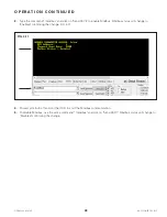
2.
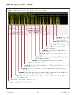
Compare the value of the background signal (column 3) against the value of the PD sensor signal (Column 4).
The PD sensor signal should have a value of at least 500 counts higher than the background signal. If these two
values have the specified difference, continue to the next step. If not, contact KAM Technical Support for further
assistance.
3.
Verify that the value of the LED Off signal (column 5) is between 0 and 150 and the value of the LED On signal
(Column 6) is between 500 and 1,024. If the values of these signals are within the stated limits, continue to the
next step. If not, contact KAM Technical Support for further assistance.
4.
Verify the value of the PD sensor voltage as follows:
For Serial Numbers OOD-19-140 or lower: Column 8 should have a value in between 28,000 and 45,000.
For Serial Numbers OOD-19-141 or higher: Column 7 should be in between 47.0 and 57.0 volts.
If the voltage is within the stated limits, continue to the next step. If not, contact KAM Technical Support for
further assistance.
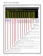
5.
Use a multimeter in ammeter mode to measure the output current loop across the 4-20 mA+ and 4-20 mA-
terminals on the top board. This voltage should match the value of the 4-20 mA current output (column 12)
displayed on RealTerm. If the values do not match, please contact Kam Technical Support for further assistance.
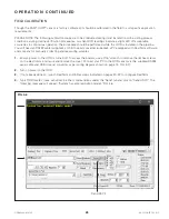
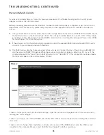
RS485 COMMUNICATION
The following procedure is to be conducted in cases where the Power Connections, RS232 Communication and
Electronics Debugging sections’ steps have been performed, but there is no RS485 communication with the PLC/
computer.
1.
Ensure the Modbus settings are configured according to the instructions on page 30 of this manual and verify
that the RS485 converter (Not provided) is installed on your PC as per the device’s user manual.
2.
Connect the RS485 converter to the OOD per the wiring diagram on page 14 of this manual.
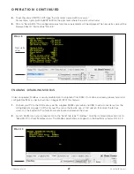
3.
Use a multimeter in voltmeter mode to measure the voltage between the 485 TX and 485 RX on the terminal
board. The differential voltage is usually around 2 volts. Continue to the next step.
NOTE: The RS485+ and RS485- lines in two wire mode are differential, so their voltage needs to me measured
with respect to each other to conform to the RS485 standards. The bias is provided by the master device.
4.
Ensure the OOD and PLC/Computer are connected properly as per the RS485 converter’s user manual.
5.
Check the activity LEDs on the RS485 converter connected to the RS485 terminals of the OOD. The LEDs should
be blinking while data is being sent/received.
6.
If there is no differential voltage or there is no activity on the LED (if available) of the RS485 converter, contact
KAM Technical Support for further assistance.
T R O U B L E S H O O T I N G C O N T I N U E D


