14
OODMANUAL 0720
KAM CONTROLS, INC.
I N S TA L L AT I O N C O N T I N U E D
WIRING CONTINUED
1.
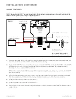
To access the boards, use a 7/16" wrench to remove the (6) screws on the electronics enclosure and remove the
cover. Ensure that power to the OOD is turned off before proceeding.
2.
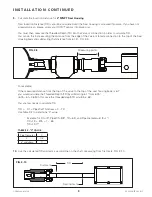
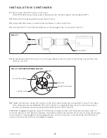
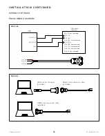
To ground the OOD™ sensor, connect the chassis ground on the OOD™ board labeled "CHS GND" on the OOD™
Terminal Block (FIG. 3-17) to earth ground either through the pipeline or appropriate low impedance buried
grounding structure, using 16 AWG braided wire.
NOTE: CHS is isolated from GND. Grounding CHS to pipeline through the grounding screw will not short OOD™
GND to the pipeline.
3.
Prior to connecting power for the OOD™ sensor, first check both wires from the source for polarity and voltage,
then label appropriately. KAM recommends using shielded twisted pair wire for both power and signal.
4.
Connect positive wire to POWER (+). See FIG. 3-17.
5.
Connect negative wire to POWER (-). See FIG. 3-17.
6.
Turn on power to the OOD and check voltage and polarity at the terminal block. Measurement should be close to
supply voltage.
NOTE: Grounding the OOD™ sensor through the 4-20 mA output signal and power lines will not protect the
OOD™ sensor against power surges or lightning strikes.
3.3
VD
C
O
FF
SE
T
-5
VD
C
G
AI
N
5V
D
C-
D
5V
D
C-
A
TP
5
TP
2
G
N
D
TP
7
TP
1
TP
3
TP
4
3939 ANN ARBOR DRIVE
HOUSTON TX - 77063
Tel. +1-713-784-0000
Fax: + 1-713-784-0001
www.Kam.com
KAM OOD
MADE IN USA
RS232 RXD
CHS GND
RS232 TXD
GND
POWER (+)
POWER (-)
485 RX
485 TX
DIGITAL OUT
CHS GND
4-20 mA (+)
4-20 mA (-)
CAUTION: OOD provides the power
for the 4-20 mA load.
Do NOT apply external voltage, as
this will damage the 4-20 mA output.
500 Ohm
max load
KAM serial cable
(diagnostics only)
12 or 24 VDC (5 Watts)
power supply
FIG. 3-17
To grounding rod (preferred)
or enclosure
Modbus/RS485 serial connections


