


10
OODMANUAL 0720
KAM CONTROLS, INC.
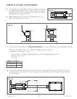
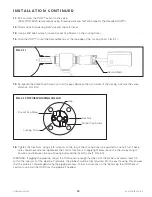
15.
Re-tighten the Socket Cap Screws so that the gaps between the two halves of the locking collar are the same
distance. FIG. 3-12.
11.
Bolt or screw the OOD™ sensor to the valve.
(KAM CONTROLS recommends using thread sealant and not Teflon tape for the threaded OOD™).
12.
Slowly open Full-opening Ball Valve and check for leaks.
13.
Using a 3/8" Allen wrench, loosen Socket Cap Screws on the Locking Collar.
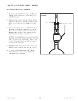
14.
Push the OOD™ in until the Second Mark is at the top edge of the Locking Collar. FIG. 3-11.
FIG. 3-11
I N S TA L L AT I O N C O N T I N U E D
Second Mark
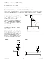
16.
Tighten the Hex Nuts, using a 3/4" wrench, on the top of the Locking Collar one quarter to one half turn. These
nuts should never be over tightened. Their major function is to apply light pressure on the chevron packing to
ensure a seal between the seal housing body and the insertion shaft. FIG. 3-12.
WARNING: If pigging the pipeline, retract the OOD sensor enough that the tip of the probe is located at least 1/4"
within the inner wall of the pipeline. Preferably, the probe should be fully retracted into the seal housing. This ensures
that the probe is not damaged during the pigging process. Follow instructions on the "Removing the OOD Sensor"
section to uninstall the OOD from the pipeline if needed.
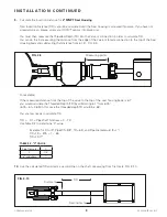
SECTION A-A
SCALE 1 / 2
1
1
2
2
A
A
B
B
MATERIAL
FINISH
DRN
THIS DRAWING IN DESIGN AND
DETAIL IS THE PROPERTY OF
KAM CONTROLS INCORPORATED.
IT SHALL NOT BE REPRODICED
AND SHALL BE RETURNED TO US
ON DEMAND
ALL RIGHTS RESERVED
APPVD
SCALE
DATE
DWG NO.
REV
TITLE
UNLESS OTHERWISE
SPECIFIED
ALL DIM IN INCHES
ANGULAR TOL ±1/2
FRACTIONAL TOL ±1/64
3 PLACE DEC ±0.005
2 PLACE DEC ±0.010
REMOVE ALL BURRS
BREAK SHARP EDGES
DO NOT SCALE DWG
SHEET
SS316
Gerry Alejos
1:2
03-13-2013
A
2"-150 Seal Housing
Assembly
211-001-000
Kam
Controls
Incorporated
3939 Ann Arbor Dr.
Houston TX 77063
USA
WWW.KAM.COM
1
OF 1
A
1/4
5/32
FIG. 3-12 TOP VIEW LOCKING COLLAR
Socket Cap Screw
Socket Cap Screw
Locking Collar
Gap
Hex Nut


