background image

30

OODMANUAL 0720

KAM CONTROLS, INC.

1. 

If you haven't already done so, follow instructions on the "Enabling/Disabling Modbus" on pages 27-28 of this 

manual to enable Modbus.

2. 

Ensure power to the OOD is turned off. 

3. 

Set any jumpers on the RS485 converter to use two-wire mode.

4. 

To access the boards, use a 7/16" wrench to remove the (6) hex screws on the electronics enclosure and remove 

the cover. 

5. 

Hook up the 485 TX terminal on the OOD's top board to Data(+) line on the RS485 converter. FIG. 4-14.

6. 

Hook up the 485 RX terminal on the OOD's top board to the Data(-) line on the RS485 converter. FIG. 4-14.

O P E R AT I O N   C O N T I N U E D

RECOMMENDED RS485 CONNECTIONS

7. 

Make sure the activity indicator (when available) on the converter blinks as data is transferred or read by the 

Modbus master reader software.

8. 

Set the appropriate COM port in the Modbus software. This setting varies with the system and whether the 

connection to the converter is connected to the serial communications port or to the USB port. Follow converter 

manufacturer's recommendations for settings.

9. 

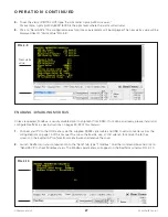
Use the following configuration settings in the Modbus software:

Mode: RTU 

Baud Rate: 9600 

Data Bits: 8 

Stop Bits: 1 

Parity: None 

Function Code: 3 

Slave ID: 1 (By default, the Slave ID or Modbus Address is set to 1. To change Modbus address see "Changing  


         Modbus Address" section on page 29 if necessary). 

Offset: 0 

FIG. 4-14 RS485 WIRING DIAGRAM

TDA(-)/ DATA -
TDB(+)/ DATA +

RS-485 Converter 

(2-Wire)

OOD

485 RX

485 TX

RS485 Wiring Diagram

Содержание Simple Presision OOD FT Flow Through

Страница 1: ...784 0000 FAX 1 713 784 0001 Email Sales Kam com KAM CONTROLS INC 3939 Ann Arbor Drive Houston Texas 77063 USA www KAM com User Manual KAM OOD OPTICAL OIL DETECTOR OODMANUAL 0720 An ISO 9001 certified...

Страница 2: ...12 Flanged Fixed Insertion 12 Wiring 13 4 Operation 20 Communication Software Configuration 20 Output Data 22 Field Calibration 25 Setting the Alarm Setpoint 26 Enabling Disabling Modbus 27 Changing t...

Страница 3: ...ion flexibility Measurement is completely automatic without the need for operator intervention or supervision and the output signal can be sent to the SCADA PLC s or to a central control room for logg...

Страница 4: ...F 40 to 80 C Electronics temp 4 to 140 F 20 to 60 C Pressure ratings ANSI 150 300 600 900 Threaded models 3 4 1 MNPT designed maximum working pressure of 2100 psig Mounting 2 MNPT seal housing 2 3 or...

Страница 5: ...trument must be installed on a T or analyzer loop with a minimum distance of 6 before any bends reducers elbows valves etc FIG 3 2 PLEASE NOTE In all KAM OOD installations the user should ensure that...

Страница 6: ...raight portion of pipe It needs to be mounted off the bend opposite the pump DO NOT install the OOD sensor with the lens facing directly into the flow If the product has particulate matter in the flui...

Страница 7: ...S TA L L AT I O N C O N T I N U E D INSTALLATION DO S AND DON TS DO NOT use teflon tape on the OOD sensor threads DO use liquid thread sealant DO install the OOD sensor with a sunshade if the electro...

Страница 8: ...Loosen the Socket Cap Screws using a 3 8 Allen wrench on the locking collar This will allow the OOD shaft to slide through the seal housing 3 Push the OOD back through the seal housing until the OOD p...

Страница 9: ...ion Distance TID D1 Pipe Wall Thickness Seal Thickness X Use Table 3 1 to determine X value Example for D1 19 Pipe WT 3 8 Seal Thickness 1 8 and Pipe Diameter 6 X 1 TID 19 375 125 1 TID 20 5 7 FIG 3 7...

Страница 10: ...the Seal Housing body and subtracting that distance from 6 75 FIG 3 9 First mark Second mark FIG 3 10 TID Measuring points For example If the measured distance from the top of the valve to the top of...

Страница 11: ...WARNING If pigging the pipeline retract the OOD sensor enough that the tip of the probe is located at least 1 4 within the inner wall of the pipeline Preferably the probe should be fully retracted int...

Страница 12: ...cases where line pressure cannot be reduced below 100 psi a KAM IT Insertion Tool must be used to safely remove the unit CAUTION Once the Socket Cap Screws have been loosened the OOD shaft may push o...

Страница 13: ...be lens rather than rushing directly at the probe If the OOD is installed with the product rushing directly at the probe particles in the pipeline can scratch the lens causing abrasions and resulting...

Страница 14: ...he requirements at least of the standard conditions indicated on the cover sheet of the referenced ATEX certification and for which a separate test certificate is available Thereby the operating condi...

Страница 15: ...s using shielded twisted pair wire for both power and signal 4 Connect positive wire to POWER See FIG 3 17 5 Connect negative wire to POWER See FIG 3 17 6 Turn on power to the OOD and check voltage an...

Страница 16: ...the 4 20mA output OOD TYPICAL WIRING POWER POWER 4 20mA 4 20mA 24VDC 5 Watts POWER SUPPLY RECEIVER INPUT OOD I N S TA L L AT I O N C O N T I N U E D WIRING CONTINUED TYPICAL POWER AND LOOP WIRING CONF...

Страница 17: ...wered Isolator Power Supply and Output Wiring with Loop Powered Isolator Reco Recommended 4 20mA Lo 1 ASI X756526 Loop Power DIN Rail Slim Line Single Ch 2 ASI 451129 4 20mA Loop Isolator Single Chann...

Страница 18: ...C O N T I N U E D WIRING CONTINUED FIG 3 21 24 VDC TYPICAL WIRING WRONG WIRING OOD Digital Out Low Side High Side Relay GND WRONG WIRING Relay GND Digital Out Low Side OOD High Side AC Voltage Low Si...

Страница 19: ...D Pin 6 DSR Not connected Pin 7 CTS Not connected Pin 8 RTS Not Connected Pin 9 RI Not Connected RS232 TXD RS232 RXD RS232 GND RS232 WIRING DIAGRAM I N S TA L L AT I O N C O N T I N U E D WIRING CONTI...

Страница 20: ...20mA OOD POWER SUPPLY 24VDC 5 Watts Recommended 4 20mA Loop Is 1 ASI X756526 Loop Powered Ana DIN Rail Slim Line Single Channel 2 ASI 451129 4 20mA Loop Power Isolator Single Channel DIN Rail LCD Mode...

Страница 21: ...move the cover 1 An RS232 cable for connecting your PC to the OOD has been supplied with the OOD as well as a USB to serial converter in case your computer does not have an RS232 serial port If you ha...

Страница 22: ...200 Parity None Data Bits 8 Stop Bits 1 Hardware Flow Control None Port Select port number assigned to your serial port or USB port connected to converter 6 Click on the Change button to save these se...

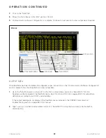
Страница 23: ...Software Configuration section please follow the steps below to view output data 1 Go to the Send tab type ostart c 20 on the first command box and click on Send ASCII FIG 4 3 Readings will be display...

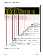
Страница 24: ...lue to 65 535 Column 5 LED Off signal Shows the value of the LED light source when it is off Range 0 to 150 Column 6 LED On signal Shows the value of the LED light source when it is on Range 500 to 1...

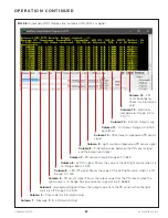
Страница 25: ...nd sensor signal value to 65 535 Column 5 LED Off signal Shows the value of the LED light source when it is off Range 0 to 150 Column 6 LED On signal Shows the value of the LED light source when it is...

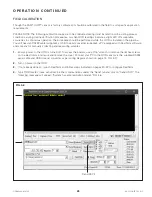
Страница 26: ...232 cable supplied a USB to serial converter supplied a PC equipped with RealTerm software and a means for manually collecting and measuring samples 1 Ensure power to the OOD is turned off To access t...

Страница 27: ...ed as per instructions on the Communication Software Configuration section on pages 20 22 1 Ensure power to the OOD is turned off To access the boards use a 7 16 wrench to remove the 6 hex screws on t...

Страница 28: ...ally disabled prior to shipment from KAM If not done so already please install and configure RealTerm as per instructions on pages 20 22 of this manual 1 Connect your PC to the OOD sensor via the supp...

Страница 29: ...status will change to Enabled confirming the change FIG 4 11 O P E R AT I O N C O N T I N U E D FIG 4 11 4 Power cycle turn off and on the OOD to start the Modbus communication 5 To disable Modbus use...

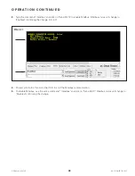
Страница 30: ...manual 2 Follow instructions to install and configure RealTerm on pages 20 22 of this manual 3 Type OODmaster case sensitive in either command box and click on Send ASCII FIG 4 12 There will be a ret...

Страница 31: ...RS485 CONNECTIONS 7 Make sure the activity indicator when available on the converter blinks as data is transferred or read by the Modbus master reader software 8 Set the appropriate COM port in the M...

Страница 32: ...Float LED OFF status 42005 32bit Float LED ON status 42006 32bit Float Electronics temperature in Celsius 42008 32bit Float 4 20mA output 42009 32bit Float Oil content in ppm OOD Modbus Registers 11 C...

Страница 33: ...e instructions to uninstall or remove the OOD from the pipeline page 11 and place the OOD on a flat surface Use a clean cloth with oil solvent or part washer to carefully clean the lens at the tip of...

Страница 34: ...ge terminals 1 Use a multimeter in voltmeter mode to measure the voltage across the power loop terminals POWER and POWER The voltage should be within the instrument s requirements 12 V to 24 V and clo...

Страница 35: ...utput loop by following the procedure below 1 Use a small screwdriver to disconnect the wires connected to the 4 20 mA terminals from the Terminal Board 2 Using a multimeter in voltmeter mode measure...

Страница 36: ...ithin the stated range proceed to connect the supplied RS232 serial cable and USB to serial converter to your computer and launch RealTerm T R O U B L E S H O OT I N G C O N T I N U E D 3 The RS232 se...

Страница 37: ...ELECTRONICS DEBUGGING The following procedure is to be conducted in cases where the Power Connections 4 20 mA Output Loop and RS232 Communication sections steps have been performed but the output is n...

Страница 38: ...alues do not match please contact Kam Technical Support for further assistance RS485 COMMUNICATION The following procedure is to be conducted in cases where the Power Connections RS232 Communication a...

Отзывы: