LRWMANUAL 0918
KAM CONTROLS, INC.
7
I N S TA L L AT I O N c o n t i n u e d
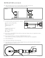
Measure the calculated MID from the top of the Locking Collar and place a mark with a permanent marker or
tape on the Shaft. FIG. 3-6.
Bolt or screw the LRW sensor to the valve or designated installation location.
(KAM CONTROLS recommends using thread sealant and not Teflon tape for the threaded LRW).
Open full opening valve.
Loosen Socket Cap Screws on the locking collar.
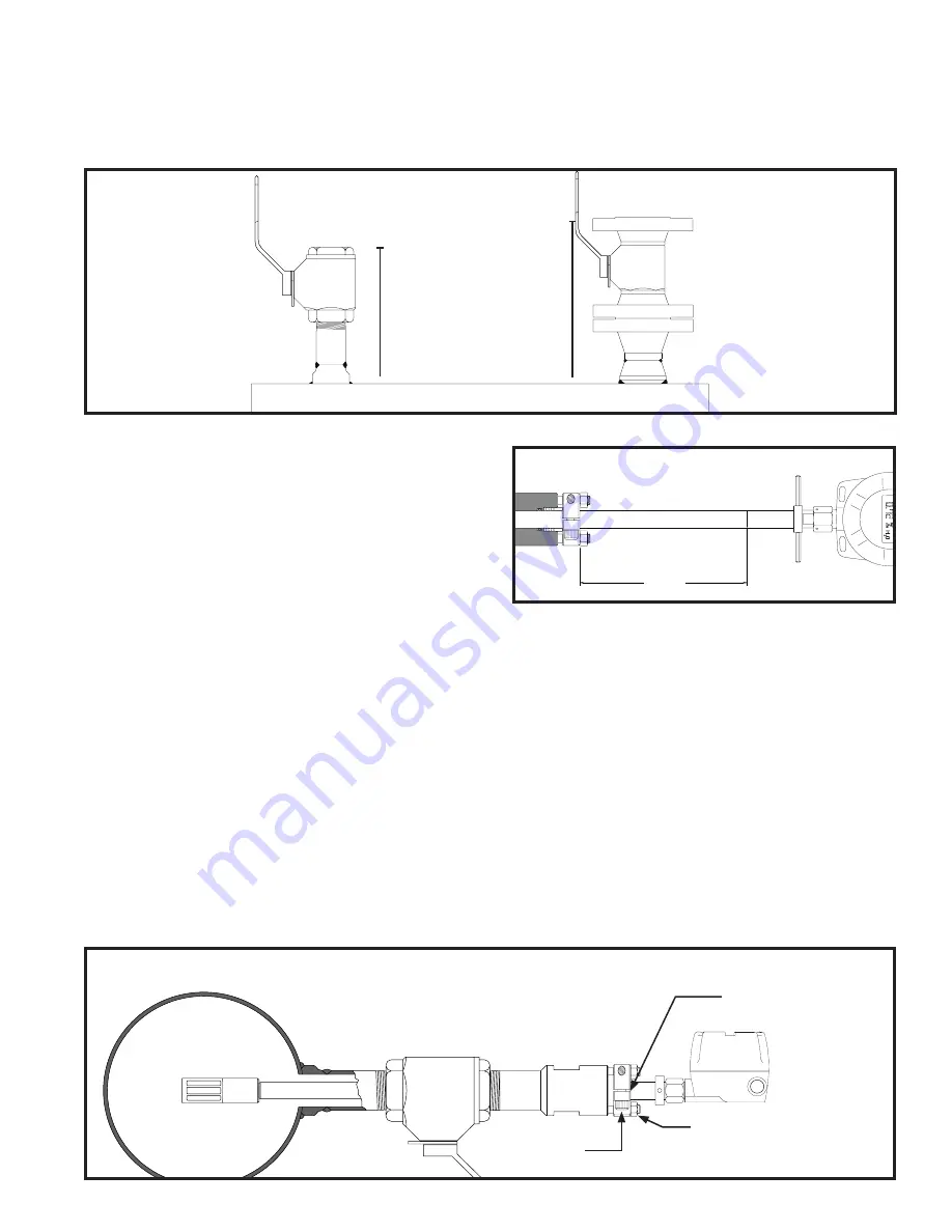
Push LRW sensor in until the mark is at the top edge of the locking collar. Ensure that LRW flow indicator is
aligned with pipeline flow direction. FIG. 3-7.
5.
MID
6.
7.
8.
FIG. 3-6
9.
Calculate the minimum insertion distance for the LRW.
Minimum insertion distance (MID) =
D1 +
Pipe Wall Thickness (WT) +
Gasket Thi
3"
Example for D1=16", WT =1/4",
Gasket Thickness=1/8"
MID = 16 + 1/4 + 1/8 + 3
MID = 19 3/8"
4.
Measure the distance (D1) from the outside diameter of main pipe to the end of the
connection where the LRW sensor is going to be installed. FIG. 3-5.
D1
D1
3.
FIG. 3-5
FIG. 3-7
Mark
Hex Nuts
Socket
cap screws

