LRWMANUAL 0918
KAM CONTROLS, INC.
30
CHECKING 5V DC SUPPLY
Once the LRW input power has been verified as per instructions above, proceed to check the 5V DC supply:
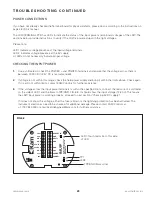
Check LED2. If lit, power is flowing to the 5V circuit.
Proceed to verify the level of this 5V supply by connecting the red wire of the multimeter to TP1 and black wire
to TP3 (GND) Terminal. FIG. 6-3.
The DC voltage should read between 4.95V and 5.05V. This means the power supplies are operational, there
could be a fault in the other systems of the instrument. Contact KAM Technical Support for further assistance.
If the voltage is not within limits, the 5V power supply is nonfunctional. Return to the factory for repair.
If LED2 does not light up, the 5V DC supply may be damaged. Please contact KAM Technical Support at +1 713
784 0000 or [email protected] for further assistance.
1.
2.
3.
4.
5.
T R O U B L E S H O O T I N G C O N T I N U E D
The LRW supplies power for the loop. Make sure the device that receives data from the LRW does not have a
power source of its own switched on. Also, the LOOP+ and LOOP- are isolated inputs from the chassis/earth. Do
not connect either to a common ground. Use an isolator if necessary.
Check the voltage across the LOOP+ and LOOP- terminals on the Terminal Board. It should read between 10V
and 12V. If not, contact KAM Controls for further assistance.
If the voltage across the Loop terminals is within the specified limits, make sure the loop is working properly by
switching the multimeter to ammeter mode and checking the current running through it without a load. The
current must correspond with the readings on the LCD display:
If it does, the 4-20mA wire from the LRW to the PLC may be damaged.
If it doesn't, contact KAM Technical Support for further assistance.
LOOP TROUBLESHOOTING
1.
2.
3.
If you have not already done so, follow the steps on page 28 of this manual to remove LCD cover and faceplate.
If the Loop water reading does not match the water % reading on the LRW local display, please follow
these instructions:

