LRWMANUAL 0918
KAM CONTROLS, INC.
9
I N S TA L L AT I O N c o n t i n u e d
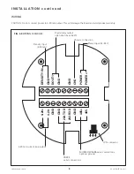
WIRING
DENSIT
Y IN
4-20+
4-20-
GND
GND
GND
GND
485+
232-TXD
232-RXD
485-
DOUT1
GND
GND
CHS
PO
WER-
PO
WER+
FIG. 3-9
WIRING DIAGRAM
4-20 mA current loop output
LCD connector
Density input
(4-20 mA)
Digital relay output
open drain (max 50 W)
Power input (12-24 V)
Chassis connection
RS232
serial connections
MODBUS/RS485 serial connections
optional ground
CAUTION: Do not connect power to 4-20 mA output. This will damage the board and void product warranty.

