Automatic Gas Console Advanced Functions FineLine 200PC User’s Manual
Setting the Pierce Delay Time
After the FineLine cutting arc transfers to the workpiece, a motion signal (ok to
move signal) is sent to the x/y controller or torch height control. The time delay
between arc transfer and the motion signal output can be adjusted with the Pierce
Delay Time parameter. The pierce delay is usually adjusted so the arc fully
penetrates the plate before the motion output signal is generated. Depending on
the status of the Default Delay parameter (see below), a default pierce delay time
can be automatically retrieved after a material type and thickness are entered, or
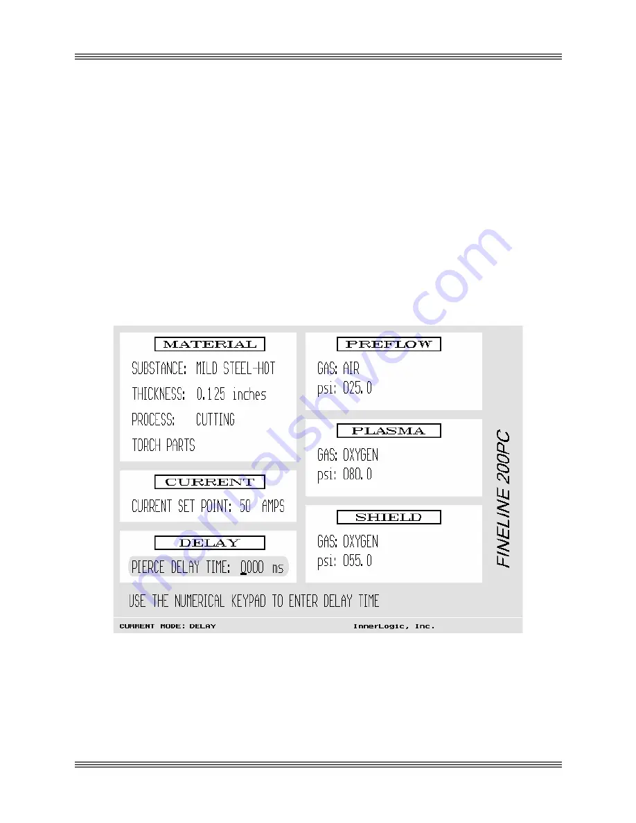
the delay time can be entered manually. To alter the pierce delay time, use the
arrow keys to scroll to Pierce Delay Time. The pierce time should be highlighted
as shown in Figure 5-2 and the editing cursor should be blinking. Use the
numerical keypad to enter the desired pierce delay time. Note that the units are in
milliseconds (1000 milliseconds = 1 second). Use the CLR key to backspace if an
error is made. When the correct value has been entered, press ENT. Note that the
maximum allowable pierce delay time is 5000 milliseconds (5 seconds).
Figure 5-2 Setting the Pierce Delay Time
5-2
Содержание FineLine 200PC
Страница 2: ...This page intentionally left blank ...
Страница 10: ...This page intentionally left blank ...
Страница 24: ...This page intentionally left blank ...
Страница 31: ...Installation FineLine 200PC User s Manual Figure 3 3 Power Supply Output Connections 3 7 ...
Страница 33: ...Installation FineLine 200PC User s Manual Figure 3 4 Torch Leads to RHF Console Connections 3 9 ...
Страница 36: ...Installation FineLine 200PC User s Manual Figure 3 5 Torch Connections 3 12 ...
Страница 42: ...This page intentionally left blank ...
Страница 124: ...Maintenance and Troubleshooting FineLine 200PC User s Manual Figure 7 3 Chopper Diagnostics Part 1 7 14 ...
Страница 125: ...Maintenance and Troubleshooting FineLine 200PC User s Manual Figure 7 4 Chopper Diagnostics Part 2 7 15 ...
Страница 126: ...This page intentionally left blank ...
Страница 130: ...Parts List FineLine 200PC User s Manual Figure 8 2 Power Supply Rear View 8 4 ...
Страница 131: ...Parts List FineLine 200PC User s Manual Figure 8 3 Power Supply Left Side View 8 5 ...
Страница 132: ...Parts List FineLine 200PC User s Manual Figure 8 4 Power Supply Right Side View 8 6 ...
Страница 134: ...Parts List FineLine 200PC User s Manual Figure 8 5 Remote High Frequency Console 8 8 ...
Страница 146: ...Parts List FineLine 200PC User s Manual QUICK DATA Figure 8 16 Gas Console Exterior 8 20 ...
Страница 147: ...Parts List FineLine 200PC User s Manual Figure 8 17 Gas Console Interior 8 21 ...
Страница 149: ...Parts List FineLine 200PC User s Manual A C Detect P C Board Assembly 500810 Figure 8 19 A C Detect P C Board 8 23 ...
Страница 150: ...Parts List FineLine 200PC User s Manual Relay P C Board Assembly 500348 Figure 8 20 Relay P C Board 8 24 ...
Страница 157: ...Propylene Glycol MSDS FineLine 200PC User s Manual Appendix A Propylene Glycol MSDS A 1 ...
Страница 158: ...Propylene Glycol MSDS FineLine 200PC User s Manual A 2 ...
Страница 159: ...Propylene Glycol MSDS FineLine 200PC User s Manual A 3 ...
Страница 160: ...Propylene Glycol MSDS FineLine 200PC User s Manual A 4 ...
Страница 161: ...Propylene Glycol MSDS FineLine 200PC User s Manual A 5 ...
Страница 162: ...Propylene Glycol MSDS FineLine 200PC User s Manual A 6 ...
Страница 163: ...Propylene Glycol MSDS FineLine 200PC User s Manual A 7 ...
Страница 164: ...Propylene Glycol MSDS FineLine 200PC User s Manual A 8 ...
Страница 168: ...This page intentionally left blank ...
Страница 171: ...Hydrogen Manifold Optional FineLine 200PC User s Manual Figure C 2 Hydrogen Manifold Mounting Location C 3 ...


