


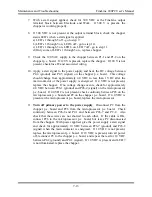


Maintenance and Troubleshooting FineLine 200PC User’s Manual
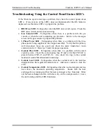
General Troubleshooting
The following chart lists general troubleshooting guidelines for the FineLine
system when the status LED’s or the automatic gas console messages screen do
not give any insight to the particular problem being experienced. Please contact
KALIBURN technical support for any issues not covered in this section. Before
any tests are performed, make sure that all system fuses are good. The primary
system fuse F1 is located on the rear panel of the unit. All of the control fuses are
located behind the front panel of the unit beside the microprocessor p.c. board.
The automatic gas console fuse is located behind the right side panel of the
system. Also check all of the voltage LED’s on the system p.c. boards before
performing any tests.
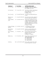
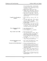
Problem Possible
Cause
Front panel white A.C. power light will
not illuminate
1. Primary disconnect fuse blown.
2. Fuse F1 or F4 blown.
3. White light or associated wiring bad.
4. Transformer TR2 or associated wiring bad.
Unit will not energize when the ON
button is pressed
1. RHF door open.
2. Low coolant level.
3. Fuse F4 blown.
4. Faulty ON switch or associated wiring. The
ON switch is normally open.
5. Faulty OFF switch or associated wiring. The
OFF switch is normally closed.
6. Relay CR1 coil open.
Power supply will not stay on when the
front panel ON button is pressed and
released
1. Check the control panel status LED’s and
troubleshoot accordingly.
2. Check the gas console messages screen and
troubleshoot accordingly.
3. Faulty latch relay on relay p.c. board.
4. Faulty relay p.c. board.
5. Faulty microprocessor p.c. board.
6. Relay CR1 defective.
No arc at the torch
1. Incorrect torch consumables installed.
2. Incorrect gas pressure settings.
3. Check the control panel status LED’s and
troubleshoot accordingly.
4. Check the spark gap assembly inside the RHF
console for proper arcing after a start signal is
applied. Open the RHF door and pull up on
the door interlock switch plunger to defeat the
interlock. If there is no spark, skip to the next
test.
5. Check the automatic gas console messages
screen and troubleshoot accordingly. If the
“output voltage low” error is present, perform
the chopper test in this section.
6. Pilot arc resistor PAR or pilot arc transistor
7-10
Содержание FineLine 200PC
Страница 2: ...This page intentionally left blank ...
Страница 10: ...This page intentionally left blank ...
Страница 24: ...This page intentionally left blank ...
Страница 31: ...Installation FineLine 200PC User s Manual Figure 3 3 Power Supply Output Connections 3 7 ...
Страница 33: ...Installation FineLine 200PC User s Manual Figure 3 4 Torch Leads to RHF Console Connections 3 9 ...
Страница 36: ...Installation FineLine 200PC User s Manual Figure 3 5 Torch Connections 3 12 ...
Страница 42: ...This page intentionally left blank ...
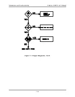
Страница 124: ...Maintenance and Troubleshooting FineLine 200PC User s Manual Figure 7 3 Chopper Diagnostics Part 1 7 14 ...
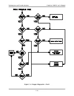
Страница 125: ...Maintenance and Troubleshooting FineLine 200PC User s Manual Figure 7 4 Chopper Diagnostics Part 2 7 15 ...
Страница 126: ...This page intentionally left blank ...
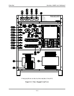
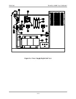
Страница 130: ...Parts List FineLine 200PC User s Manual Figure 8 2 Power Supply Rear View 8 4 ...
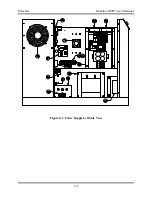
Страница 131: ...Parts List FineLine 200PC User s Manual Figure 8 3 Power Supply Left Side View 8 5 ...
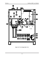
Страница 132: ...Parts List FineLine 200PC User s Manual Figure 8 4 Power Supply Right Side View 8 6 ...
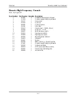
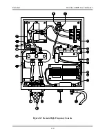
Страница 134: ...Parts List FineLine 200PC User s Manual Figure 8 5 Remote High Frequency Console 8 8 ...
Страница 146: ...Parts List FineLine 200PC User s Manual QUICK DATA Figure 8 16 Gas Console Exterior 8 20 ...
Страница 147: ...Parts List FineLine 200PC User s Manual Figure 8 17 Gas Console Interior 8 21 ...
Страница 149: ...Parts List FineLine 200PC User s Manual A C Detect P C Board Assembly 500810 Figure 8 19 A C Detect P C Board 8 23 ...
Страница 150: ...Parts List FineLine 200PC User s Manual Relay P C Board Assembly 500348 Figure 8 20 Relay P C Board 8 24 ...
Страница 157: ...Propylene Glycol MSDS FineLine 200PC User s Manual Appendix A Propylene Glycol MSDS A 1 ...
Страница 158: ...Propylene Glycol MSDS FineLine 200PC User s Manual A 2 ...
Страница 159: ...Propylene Glycol MSDS FineLine 200PC User s Manual A 3 ...
Страница 160: ...Propylene Glycol MSDS FineLine 200PC User s Manual A 4 ...
Страница 161: ...Propylene Glycol MSDS FineLine 200PC User s Manual A 5 ...
Страница 162: ...Propylene Glycol MSDS FineLine 200PC User s Manual A 6 ...
Страница 163: ...Propylene Glycol MSDS FineLine 200PC User s Manual A 7 ...
Страница 164: ...Propylene Glycol MSDS FineLine 200PC User s Manual A 8 ...
Страница 168: ...This page intentionally left blank ...
Страница 171: ...Hydrogen Manifold Optional FineLine 200PC User s Manual Figure C 2 Hydrogen Manifold Mounting Location C 3 ...


