Operation
FineLine 200PC User’s Manual
4-10
cap and clean as necessary.
5. Install a small amount of o-ring lubricant to the three o-rings on the torch
body.
6. Apply a small amount of o-ring lubricant to the retaining cap o-ring and install
the retaining cap onto the torch body. Tighten the cap firmly but do not over
tighten.
7. Apply a small amount of o-ring lubricant to the shield cap o-ring and install
the shield cap into the brass outer cap.
Note: Make sure the shield cap o-
ring is seated properly inside the outer cap
.
8. Install the outer cap onto the torch body and tighten firmly. Do not over
tighten.
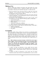
Viewing Recommended Height Control and X/Y Machine Settings
Prior to making a cut with the system, the torch height control and the x/y cutting
machine must be configured properly. To view the recommended cutting data,
press the Menu key, then Voltage. The voltage screen will be displayed as shown
in Figure 4-9. The x/y machine speed should be set to the value shown. Also, the
height control should be set to the proper pierce height, cutting height and arc
voltage. If a KALIBURN Inova height control is being used, simply press the F3
key to automatically transmit the parameters to the Inova.
Figure 4-9 Voltage Screen
Содержание FineLine 200PC
Страница 2: ...This page intentionally left blank ...
Страница 10: ...This page intentionally left blank ...
Страница 24: ...This page intentionally left blank ...
Страница 31: ...Installation FineLine 200PC User s Manual Figure 3 3 Power Supply Output Connections 3 7 ...
Страница 33: ...Installation FineLine 200PC User s Manual Figure 3 4 Torch Leads to RHF Console Connections 3 9 ...
Страница 36: ...Installation FineLine 200PC User s Manual Figure 3 5 Torch Connections 3 12 ...
Страница 42: ...This page intentionally left blank ...
Страница 124: ...Maintenance and Troubleshooting FineLine 200PC User s Manual Figure 7 3 Chopper Diagnostics Part 1 7 14 ...
Страница 125: ...Maintenance and Troubleshooting FineLine 200PC User s Manual Figure 7 4 Chopper Diagnostics Part 2 7 15 ...
Страница 126: ...This page intentionally left blank ...
Страница 130: ...Parts List FineLine 200PC User s Manual Figure 8 2 Power Supply Rear View 8 4 ...
Страница 131: ...Parts List FineLine 200PC User s Manual Figure 8 3 Power Supply Left Side View 8 5 ...
Страница 132: ...Parts List FineLine 200PC User s Manual Figure 8 4 Power Supply Right Side View 8 6 ...
Страница 134: ...Parts List FineLine 200PC User s Manual Figure 8 5 Remote High Frequency Console 8 8 ...
Страница 146: ...Parts List FineLine 200PC User s Manual QUICK DATA Figure 8 16 Gas Console Exterior 8 20 ...
Страница 147: ...Parts List FineLine 200PC User s Manual Figure 8 17 Gas Console Interior 8 21 ...
Страница 149: ...Parts List FineLine 200PC User s Manual A C Detect P C Board Assembly 500810 Figure 8 19 A C Detect P C Board 8 23 ...
Страница 150: ...Parts List FineLine 200PC User s Manual Relay P C Board Assembly 500348 Figure 8 20 Relay P C Board 8 24 ...
Страница 157: ...Propylene Glycol MSDS FineLine 200PC User s Manual Appendix A Propylene Glycol MSDS A 1 ...
Страница 158: ...Propylene Glycol MSDS FineLine 200PC User s Manual A 2 ...
Страница 159: ...Propylene Glycol MSDS FineLine 200PC User s Manual A 3 ...
Страница 160: ...Propylene Glycol MSDS FineLine 200PC User s Manual A 4 ...
Страница 161: ...Propylene Glycol MSDS FineLine 200PC User s Manual A 5 ...
Страница 162: ...Propylene Glycol MSDS FineLine 200PC User s Manual A 6 ...
Страница 163: ...Propylene Glycol MSDS FineLine 200PC User s Manual A 7 ...
Страница 164: ...Propylene Glycol MSDS FineLine 200PC User s Manual A 8 ...
Страница 168: ...This page intentionally left blank ...
Страница 171: ...Hydrogen Manifold Optional FineLine 200PC User s Manual Figure C 2 Hydrogen Manifold Mounting Location C 3 ...


