


Installation
FineLine 200PC User’s Manual
Filling the Torch Coolant Reservoir
Note: Never turn on the power supply before filling the torch
coolant reservoir with the proper coolant solution.
1. Remove the coolant reservoir cap and fill the reservoir with 2 gallons of
coolant solution.
2. Apply main power to the FineLine unit.
3. Depress and hold the green ON button on the FineLine control panel.
4. The coolant pump will begin pumping coolant fluid through the system. The
Coolant Flow LED will remain out until the coolant has filled the entire
system and begins flowing back into the tank. The coolant pump will turn off
if the coolant level drops below the minimum level inside the reservoir. If this
happens, add more coolant solution to the reservoir and return to Step 3.
6. When the Coolant Flow LED illuminates, release the green ON switch. The
FineLine system should remain energized and continue pumping coolant
through the system.
7. Locate the small red push-button on top of the coolant filter/deionization
cartridge. Depress and hold the button until no air is seen inside the clear
filter housing.
8. Fill the reservoir with coolant solution until the coolant gauge indicates full.
Coolant should be added to the system any time the level drops below half
full.
9. Check for coolant leaks at all hose connections inside the power supply, RHF
console, and at the torch.
3-17
Содержание FineLine 200PC
Страница 2: ...This page intentionally left blank ...
Страница 10: ...This page intentionally left blank ...
Страница 24: ...This page intentionally left blank ...
Страница 31: ...Installation FineLine 200PC User s Manual Figure 3 3 Power Supply Output Connections 3 7 ...
Страница 33: ...Installation FineLine 200PC User s Manual Figure 3 4 Torch Leads to RHF Console Connections 3 9 ...
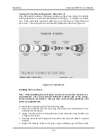
Страница 36: ...Installation FineLine 200PC User s Manual Figure 3 5 Torch Connections 3 12 ...
Страница 42: ...This page intentionally left blank ...
Страница 124: ...Maintenance and Troubleshooting FineLine 200PC User s Manual Figure 7 3 Chopper Diagnostics Part 1 7 14 ...
Страница 125: ...Maintenance and Troubleshooting FineLine 200PC User s Manual Figure 7 4 Chopper Diagnostics Part 2 7 15 ...
Страница 126: ...This page intentionally left blank ...
Страница 130: ...Parts List FineLine 200PC User s Manual Figure 8 2 Power Supply Rear View 8 4 ...
Страница 131: ...Parts List FineLine 200PC User s Manual Figure 8 3 Power Supply Left Side View 8 5 ...
Страница 132: ...Parts List FineLine 200PC User s Manual Figure 8 4 Power Supply Right Side View 8 6 ...
Страница 134: ...Parts List FineLine 200PC User s Manual Figure 8 5 Remote High Frequency Console 8 8 ...
Страница 146: ...Parts List FineLine 200PC User s Manual QUICK DATA Figure 8 16 Gas Console Exterior 8 20 ...
Страница 147: ...Parts List FineLine 200PC User s Manual Figure 8 17 Gas Console Interior 8 21 ...
Страница 149: ...Parts List FineLine 200PC User s Manual A C Detect P C Board Assembly 500810 Figure 8 19 A C Detect P C Board 8 23 ...
Страница 150: ...Parts List FineLine 200PC User s Manual Relay P C Board Assembly 500348 Figure 8 20 Relay P C Board 8 24 ...
Страница 157: ...Propylene Glycol MSDS FineLine 200PC User s Manual Appendix A Propylene Glycol MSDS A 1 ...
Страница 158: ...Propylene Glycol MSDS FineLine 200PC User s Manual A 2 ...
Страница 159: ...Propylene Glycol MSDS FineLine 200PC User s Manual A 3 ...
Страница 160: ...Propylene Glycol MSDS FineLine 200PC User s Manual A 4 ...
Страница 161: ...Propylene Glycol MSDS FineLine 200PC User s Manual A 5 ...
Страница 162: ...Propylene Glycol MSDS FineLine 200PC User s Manual A 6 ...
Страница 163: ...Propylene Glycol MSDS FineLine 200PC User s Manual A 7 ...
Страница 164: ...Propylene Glycol MSDS FineLine 200PC User s Manual A 8 ...
Страница 168: ...This page intentionally left blank ...
Страница 171: ...Hydrogen Manifold Optional FineLine 200PC User s Manual Figure C 2 Hydrogen Manifold Mounting Location C 3 ...


