Maintenance and Troubleshooting FineLine 200PC User’s Manual
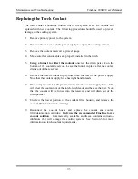
Replacing the Torch Coolant
The torch coolant should be flushed out of the system every six months and
replaced with new coolant. The following procedure should be used to prevent
damage to the cooling system.
1. Remove primary power to the system.
2. Remove the rear cover of the power supply to expose the cooling system.
3. Remove the coolant reservoir cap/level gauge.
4. Make sure that consumables are properly installed in the torch.
5.
Using a funnel to collect the coolant,
unscrew the drain petcock on the
bottom of the coolant reservoir. Leave the funnel in place after the coolant
drains out of the reservoir.
6. Remove the torch coolant supply hose from the rear of the power supply.
Note that the coolant supply hose has right hand threads.
7. Blow compressed air (100 psi maximum) into the coolant supply hose. This
will clear the coolant out of the torch, torch leads, and heat exchanger. Note
that the coolant will be forced into the reservoir and will drain out of the
drain petcock.
8. Unscrew the lower portion of the coolant filter housing and remove the
coolant filter/deionization cartridge.
9. Reconnect the coolant hoses and replace the coolant and coolant
filter/deionization cartridge.
Only use the recommended FineLine torch
coolant solution
. Commercially available antifreeze contains corrosion
inhibitors that will damage the cooling system. See Section 3 for more
information on torch coolant requirements.
7-3
Содержание FineLine 200PC
Страница 2: ...This page intentionally left blank ...
Страница 10: ...This page intentionally left blank ...
Страница 24: ...This page intentionally left blank ...
Страница 31: ...Installation FineLine 200PC User s Manual Figure 3 3 Power Supply Output Connections 3 7 ...
Страница 33: ...Installation FineLine 200PC User s Manual Figure 3 4 Torch Leads to RHF Console Connections 3 9 ...
Страница 36: ...Installation FineLine 200PC User s Manual Figure 3 5 Torch Connections 3 12 ...
Страница 42: ...This page intentionally left blank ...
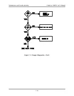
Страница 124: ...Maintenance and Troubleshooting FineLine 200PC User s Manual Figure 7 3 Chopper Diagnostics Part 1 7 14 ...
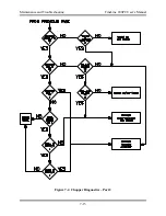
Страница 125: ...Maintenance and Troubleshooting FineLine 200PC User s Manual Figure 7 4 Chopper Diagnostics Part 2 7 15 ...
Страница 126: ...This page intentionally left blank ...
Страница 130: ...Parts List FineLine 200PC User s Manual Figure 8 2 Power Supply Rear View 8 4 ...
Страница 131: ...Parts List FineLine 200PC User s Manual Figure 8 3 Power Supply Left Side View 8 5 ...
Страница 132: ...Parts List FineLine 200PC User s Manual Figure 8 4 Power Supply Right Side View 8 6 ...
Страница 134: ...Parts List FineLine 200PC User s Manual Figure 8 5 Remote High Frequency Console 8 8 ...
Страница 146: ...Parts List FineLine 200PC User s Manual QUICK DATA Figure 8 16 Gas Console Exterior 8 20 ...
Страница 147: ...Parts List FineLine 200PC User s Manual Figure 8 17 Gas Console Interior 8 21 ...
Страница 149: ...Parts List FineLine 200PC User s Manual A C Detect P C Board Assembly 500810 Figure 8 19 A C Detect P C Board 8 23 ...
Страница 150: ...Parts List FineLine 200PC User s Manual Relay P C Board Assembly 500348 Figure 8 20 Relay P C Board 8 24 ...
Страница 157: ...Propylene Glycol MSDS FineLine 200PC User s Manual Appendix A Propylene Glycol MSDS A 1 ...
Страница 158: ...Propylene Glycol MSDS FineLine 200PC User s Manual A 2 ...
Страница 159: ...Propylene Glycol MSDS FineLine 200PC User s Manual A 3 ...
Страница 160: ...Propylene Glycol MSDS FineLine 200PC User s Manual A 4 ...
Страница 161: ...Propylene Glycol MSDS FineLine 200PC User s Manual A 5 ...
Страница 162: ...Propylene Glycol MSDS FineLine 200PC User s Manual A 6 ...
Страница 163: ...Propylene Glycol MSDS FineLine 200PC User s Manual A 7 ...
Страница 164: ...Propylene Glycol MSDS FineLine 200PC User s Manual A 8 ...
Страница 168: ...This page intentionally left blank ...
Страница 171: ...Hydrogen Manifold Optional FineLine 200PC User s Manual Figure C 2 Hydrogen Manifold Mounting Location C 3 ...


