


Country-
spec. Set-
tings
Men
u
level
Display/
Setting
Action in this menu/meaning
Dynamic reactive cur-
rent only
Off | On
Standard
: The reactive current according to the formulae (2) and (4) is
fed as
additional
reactive current. The means that sum of the pre-fault
and additional reactive current is fed in.
Only dynamic:
The reactive current according to the formulae (2) and
(4) is fed in as absolute reactive current. This means that regardless of
the reactive current before the voltage event, only the reactive current
is fed in according to the formulae (2) and (4) is fed in during the voltage
event.
Dead band mode
Mode 1 | Mode 2
Mode 1
: When calculating the reactive current, the value of the dead
band is not subtracted from the amount of voltage change.
For overvoltage and undervoltage events, formula (2) therefore applies.
Mode 2:
When calculating the reactive current, the value of the dead
band is subtracted from the amount of voltage change. For overvoltage
and undervoltage events, formula (4) therefore applies:
I
b
1
I
Minimum operating
voltage
45 – 125.0 [% Unom] /
80 [% Unom] / 0.1
&
Maximum operating
voltage
45 – 125.0 [% Unom]
80 [% Unom] / 0.1
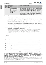
Dynamic grid support via fast feeding of residual current is activated on
voltage events with at least one phase/phase or phase/neutral conduc-
tor voltage outside the configured normal operating voltage range. Dy-
namic grid support via fast feeding ore residual current is deactivated
when the voltage returns to the normal operating voltage range.
Reactive current limita-
tion
0 – 100 [ % Imax] /
100 [ % Imax] / 1
The reactive power component of the fast feeding of residual current is
limited to permit a defined proportion of active power components.
Minimum support time
1,000 – 15,000
[ms] / 5,000 [ms]
10
If due to a voltage jump in accordance with formula (1) and the config-
ured dead band is activated, the dynamic grid support is deactivated via
fast feeding of residual current after the minimum support time elapses.
10.4
Other grid support functions effective on active power
10.4.1 Permanent power gradient limitation
The maximum active and apparent power to be installed for a generation plant is agreed between the grid op-
erator and plant operator. The device capacity of a plant can be set to the exact agreed value using the S
lim
and
P
lim
settings. To ensure that the load on the devices in the plant is uniform, we recommend distributing the per-
formance reduction evenly across all devices.
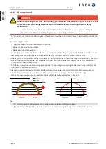
Some grid connection rules insist that the agreed reactive power be supplied from every operating point of the
plant without a reduction in the actual active power. Considering the fact that all KACO TL3 inverters have a
semi-circular(PV) full-circular(BI) P-Q operating range, a reduction in the active power is, however, required
during operation at maximum active power because an apparent power reserve is not available. By adjusting
P
lim
the maximum active power can be restricted in order to establish an apparent power reserve and ensure
Page 92] shows the appropriate P-Q operating range with a required example active power of 48%
of the maximum apparent power of the plant or 43% of the maximum active power of the plant.
Manual
Specifications | 10
KACO blueplanet 110 TL3 KACO blueplanet 125 TL3
Page 91
EN-US


