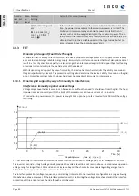
Q(U) 10 nodes
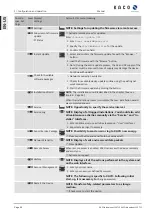
When it comes to mode Q(U), the nominal value of the reactive power is continuously calculated depending on
the grid voltage. This function ensures that grid support is provided by the reactive power as soon as the volt-
age actually deviates from the target voltage. In this case, a characteristic curve is specified which can be used
to configure up to 10 nodes, consisting of value pairs for voltage and reactive power. Other parameters allow
you to limit functionality and to limit activation to certain voltage ranges as well as parametrise the transient
response.
The zero sequence voltage is used to calculate the reactive power target for three-phase units.
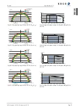
230
207
0
Q [%PN]
U[V]
Q(U) standard characteristic
0
20
40
40
20
60
253
60
1) 43,6 | 207
2) 0 | 212
3) 0 | 230
4) 0 | 248
5) 43,6 | 253
Fig. 82:
Q(U) standard characteristic curve with 5 nodes
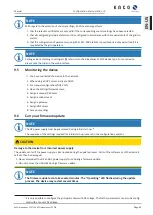
10.1.4 Parameters for reactive power control
Country-
spec. Set-
tings
Men
u
level
Display/
Setting
Action in this menu/meaning
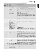
Cos-phi constant
Cos-phi constant
0,3 – 1 / 1 /
0,001
Specified power factor.
Over-excited | un-
der-excited
Reactive power mode Under-excited relates to inductive load, over-ex-
cited relates to capacitive load.
Power gradient in-
creasing & power gra-
dient decreasing
1 – 65,534 [% S
lim
/
min] / 65,534 [% S
lim
/
min] / 1
Maximum change in the reactive power %S
lim
/min in the event of a
change to over-excited mode
NOTE: The gradient is overlaid with the settling time.
Settling time
1,000 – 120,000
[ms] / 1,000 [ms]
10
Determines the dynamic behaviour in the event of a change in the cos ϕ
set value. With a reative power change, the cos ϕ is changed according
to a PT-1 characteristic curve with a settling time of 5 Tau.
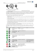
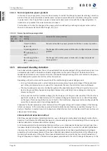
Q constant
Q constant
0 – 100 [% Slim] /
0[% Slim] / 0.1
Set as a percentage of the maximum reactive power.
Under-excited |
over-excited
Reactive power mode Under-excited relates to inductive load, over-ex-
cited relates to capacitive load.
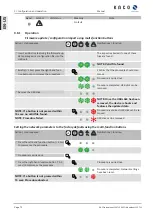
Rise Outg. grad. & Fall.
Outg. grad.
increasing | decreas-
ing
In addition to configuring the dynamic behaviour using the transient
time corresponding to a first-order filter, the reactive power setting can
be determined by a maximum gradient - this means the maximum
change in the reactive power per time period.
Manual
Specifications | 10
KACO blueplanet 110 TL3 KACO blueplanet 125 TL3
Page 79
EN-US


