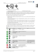


Country-
spec. Set-
tings
Men
u
level
Display/
Setting
Action in this menu/meaning
Settling time
1000 – 120,000
[ms] / 2,000 [ms] /
10 [ms]
Determines the dynamic behaviour in the event of a change in the ac-
tive power set value. With a voltage change, the active power is
changed according to a PT-1 characteristic curve with a settling time of
5 Tau.
Note:
The settling time is overlaid with the increasing and decreasing
gradient.
4
1
2
3
4
Active curve
1 - 5
F
Select the active curve.
NOTE: Up to 5 characteristic curves can be configured inde-
pendently and one of them can be activated for regulation
each time.
Number of nodes
2 - 5
Power
0.0 – 100.0 [% P
ref
] /
100.0 [% P
ref
] / 0.1
Voltage
80.0 – 126.0 [%
U
nom
] / 112.0 [%
U
nom
] / 0.1
up to 5 support points definable The power value of the first and last
value pair is also used as the maximum or minimum active power value
that is valid across the limits of the characteristic curve.
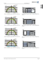
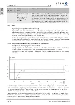
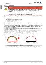
10.2.4 P(f)
P(f) Active power response to overfrequence
Feed-in inverters must assist with frequency stability in the grid. If the grid frequency leaves the normal toler-
ance range (e.g. ±200 mHz), the grid is in a critical state. In the event of overfrequency, there is a generation
surplus, in the event of underfrequency, there is a generation deficit.
PV-Systems must adapt their active feed-in power in relation to the frequency deviation. In case of overfre-
quency the adaption of power is defined by a maximum feed-in limit. The actual power of the inverter may
vary freely below this limit based on possible fluctuation of the available power or set point, but will never in-
crease above the absolute power limit.
Fig. 85:
Equation 1
Fig. 86:
Equation 2
Page 85] defines the maximum limit with ΔP according to Equation 2 [See figure
Page 85], P
M
the actual power at the moment of activation and P
ref
the reference power. In KACO PV in-
verters P
ref
is defined as P
M
, the actual power at the moment of activation. f is the actual frequency and f
1
is the
activation threshold as configured.
Fig. 87:
Equation 3
Fig. 88:
Equation 4
Manual
Specifications | 10
KACO blueplanet 110 TL3 KACO blueplanet 125 TL3
Page 85
EN-US


