background image

Mounting the Optional Door Pop Hardware Continued 

It is recommended that you leave the door panel off until the system has been tested, as 

some adjustment to the DRS may be necessary.  If you are mounting the bracket for the gas 

charged strut (GCS) to the door panel, then finish all other wiring and mounting to the point 

that the system can be tested to open the door without the GCS installed.  You can simulate 

the GCS's effect simply by applying pressure to the door with your body from the inside of 

the vehicle.   

Once you have tested and confirmed the system is working properly it is time to install the 

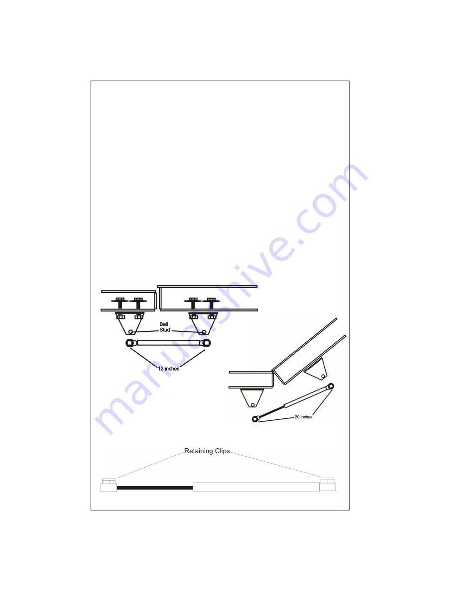
mounting brackets (DMB) and the gas charged strut (GCS).  Find a location on the vehicle's 

door post or some other strong metal surface.  This mounting location will need to handle the 

pressure of the GCS, "40lbs" over a long period of time.  Do not mount to plywood or plas-

tic!  Drill two 1/4

 holes and install using the mounting hardware provided.  With the door 

closed, measure 12 inches on the  deployment door from the point of the ball stud of the 

mounted DMB and mark it.  This will be where the ball stud of the second DMB will need to 

be located.  Align the ball stud of the second DMB with the mark and mark and drill two 

holes in the appropriate locations.  Install the second DMB with the hardware provided. 

When you are satisfied the system is work-

ing properly, close or replace any panels that 

were removed to perform the installation.  

Press fit the retaining clips on the GCS to  

prevent it from popping off. 

Page 27 

Содержание K9Caller

Страница 1: ...Installation Manual K9Caller Phone 877 K9 SAFE T Phone 877 597 2338 Located in Glendale AZ www K9Safety com K9Caller Version 1 Rev 5 Copyright K9Safety 2009 ...

Страница 2: ...age 10 Wire Connections L5 L1 Page 11 Door Lock Diagrams Page 12 Wire Connections i6 i1 Page 13 Ignition Harness Diagram Page 14 15 Connections at a Glance Page 16 Side Connectors iData Prog Temp Probe Antenna Sensor Page 17 Temperature Probe Page 18 Two Way Antenna Page 19 Program Mode extra remote Page 20 21 Programming Mode Branches Features Chart Page 22 23 Programmable Branches Features Expla...

Страница 3: ...If your installation facility does not already have access to this information you can contact our support at sup port K9Safety com and we will supply the information to you We will need to know the make model and year of the vehicle with your request Good installations always start with planning Knowing the features and options that the end user is expecting will help in planning how to install a...

Страница 4: ...how you will run the cables for the ignition harness and for the programmable temperature display CTD Planning your installation will ultimately save time and help to avoid service returns in the future A8 Orange White Disarmed Output 500ma This wire can be used to trigger a relay to close when the alarm function is disarmed A7 White Red Aux 1 Output 500mA This output can be programmed to trigger ...

Страница 5: ...r lamp output on a diesel powered vehicle This input is selectable between positive or negative sens ing The factory default is set to negative The settings are changed by changing jumper set tings on the board and in Program Branch 33 Note the polarity can be changed between negative and positive depending on the jumper setting See Fig J1 on page 9 A3 Blue Trunk Trigger Input This wire connects t...

Страница 6: ...on the meter should now show an open circuit If the circuit is still closed gradually move the contact away from the magnet until the circuit show open If you have made this adjustment test again that the circuit shows closed when in park Once properly aligned you can permanently fix the contact in place with silicone or epoxy glue Connect one of the white contact wires to chassis ground Determine...

Страница 7: ...between 3 6 volts AC Note the unit is shipped with Smart Start as the factory default Using tach sense is more reliable and is the recommended setting For this wire to be used you must change Branch 30 to option 2 and program the tach signal within Branch 31 option 1 M12 Red 12 Battery Positive Input Connect this wire to a constant 12V battery positive source capable of 15Amps M11 Black Chassis Gr...

Страница 8: ...ion is armed or disarmed if selected See Branch 21 and remote operation M5 Violet Door Trigger Input Connect this wire to a factory door pin switch or dome light trigger that shows positive when the doors are open and no positive when the doors are closed Traditionally a Ford type door trigger M4 Green Door Trigger Input Connect this wire to a factory door pin switch or dome light trigger that sho...

Страница 9: ...lenoid wire to pull the solenoid and ground the blue or to the blue wire to push and ground the green When selected as a trunk pop this wire will send the selected output only when triggered by the appropriate remote signal button 3 See program Branch 10 and Note the polarity can be changed between negative and positive depending on the jumper setting See Fig J1 below Also if both door pop and tru...

Страница 10: ... specified for the current vehicle and connect accordingly L4 White Door Lock Normally Closed Relay N C This wire is used when connecting to L3 Blue Unlock Output Relay N O This is the unlock output wire which is connected to the vehicle wire that causes the vehicle door locks to unlock There are several different types of door lock systems available on automobiles today Review the type specified ...

Страница 11: ...Lock Unlock Door Lock Connector L U Door Lock Buttons Door Lock Solenoid Green White Blue Brown Violet Battery Pos X X Note A light tester connected to ground will light when you lock unlock Wires are in drivers kick panel Negative or Positive system with factory relays L1 L5 Door Lock Relays Continued Positive reverse polarity door lock system Page 11 ...

Страница 12: ...ehicle s accessory circuit after the vehicle has auto started and during the duration of auto start and auto run i3 Brown Accessory 2 Output This wire provides a positive output to energize a vehicle s accessory circuit after the vehicle has auto started and during the duration of auto start and auto run i2 Red Battery Input 1 This is a main battery input for auto start and run functions This wire...

Страница 13: ... Violet Neg Coil Pos Coil Pos Coil Neg Coil Pin M15 Blue Orange Pin M2 Orange Common X Cut Bottom Main Connector 2nd Ignition Relay Starter Disable Anti Grind Relay Ignition Connector Top Main Connector Ignition Key Switch Ignition 2 Starter Ignition 1 Accessory 1 Accessory 2 Battery Constant Battery Constant ...

Страница 14: ...Page 14 ...

Страница 15: ...lert Delay Input Transmission In Park Input Horn Honk Output 500mA Auto Start Output 500mA Bypass Ign2 Brake Pedal Input Tachometer or Fuel Injector Input AC 3 6v 12 Battery Positive Input Chassis Ground Input Factory Alarm Disarm Ignition Output 500mA Parking Light Output selectable Hood Trigger Input shutdown Hot Temperature Alert Output 500mA Siren Output 3A Door Trigger Input Door Trigger Inpu...

Страница 16: ...ensor warn away signal when the alarm system is armed See program branch 6 S3 Black Ground Out S2 Blue External Pop Receiver Pro Impact Sensor trigger This wire can be configured to either trigger the door pop function when a ground signal is applied and the K9 system is activated or to trigger the alarm impact signal when the alarm system is armed See program branch 12 S1 Red Battery Positive Out...

Страница 17: ... system to have an inaccurate temperature reading Also if hanging the probe from the roof make sure there is a least 4 inches of wire hanging as close proximity to the roof will cause the temperature probe to sense a higher temperature level The probe comes prewired with 8 feet of cable This cable can be lengthened up to 30 ft with out adversely affecting performance Page 17 ...

Страница 18: ...ror to mount the 2 Way antenna Clean the surface of the inside of the window where mounting is to be done Remove the adhesive film cover from the pager antenna and stick on to the window The wire can be tucked under the vehicle head liner and run behind the plastic window post cover Mounting the 2 Way window Antenna ...

Страница 19: ...r every transmitter learned 4 Turn off the ignition key 5 The siren horn will chirp honk 3 times to indicate the system has exited programming mode When adding a 1 way transmitter maximum of four Any previously stored transmitter will be erased if it is not programmed within the following sequence 1 Turn the ignition key On Off On Off and back On Key On 3 times wait for the siren horn to chirp hon...

Страница 20: ...ll chirp honk to indicate the setting 1 chirp honk Button 1 2 chirps honks Button 2 3 chirps honks Button 3 4 chirps honks Button 4 5 When you are finished turn off the ignition to save the changes Some of the features should only be changed by a qualified technician These features are denoted with Tech Other feature can be changed by the user and they are denoted with User Default Reset Following...

Страница 21: ...1 Output Pin A7 Tech Branch18 Pulse Timed Latched Hot Alert Aux2 Output Pin A6 Tech Branch19 Manual Passive Alarm Arming User Branch20 Disable Enable Auto Alarm Rearm User Branch21 Siren Both Silent Arming Chirps User Branch22 No Selection Branch23 Single Double Door Unlock Pulse Tech Branch24 1 Second 3 Seconds Door Lock Pulse Length Tech Branch25 Disable Enabled Passive Door Locking Tech Branch2...

Страница 22: ... this setting via the remote control See Remote Controls h Branch 3 Temperature Alert Warning This is the setting to select the audible alert output The alert can trigger the horn alarm siren or both Branch 4 Automatic Temperature Poll The system can be set to automatically send a temperature update to the remote at regular intervals Branch 5 Alert Delay Timer The alert delay timer controls the in...

Страница 23: ...e default is 5 degrees which means if the start temperature is set to 75 degrees then the cabin has to cool to 70 degrees before the engine will shut off Branch 12 Sensor Input External Pop receiver This setting selects whether Pin S2 Blue wire will act as a door pop trigger Pro when the K9 system is activated or as a alarm sensor input Branch 13 Remote Feature Lockout This feature selects whether...

Страница 24: ... is disarmed Branch 21 Arming Chirps Selects whether the siren will chirp when the alarm system is armed disarmed This function can also be changed via the remote See Branch 22 No Selection Branch 23 Door Unlock Pulse Selects between one pulse or two pulse operation for the door unlock output Many new im port vehicles factory door locking systems require two pulses on the proper wire to unlock the...

Страница 25: ... to indicate it is reading the tach signal Press Button 1 to learn the vehicle s tach signal The siren will chirp and the LED will flash once to confirm learning of the tach signal The siren will chirp four times and the LED will flash four times if the tach signal was not learned Tach Monitor mode monitors the vehicle s tach wire or a fuel injection wire in real time to determine engine status an...

Страница 26: ...full stroke and with a center punch mark the spot of the two mounting holes of the DRS If the door latch connecting rod is pushed away from the DRS to open the door then compress the DRS to a closed stroke and use a center punch to mark the spot of the two mounting holes of the DRS Even though the system can disarm and unlock the doors before the door is popped a more reliable method of installati...

Страница 27: ...S Find a location on the vehicle s door post or some other strong metal surface This mounting location will need to handle the pressure of the GCS 40lbs over a long period of time Do not mount to plywood or plas tic Drill two 1 4 holes and install using the mounting hardware provided With the door closed measure 12 inches on the deployment door from the point of the ball stud of the mounted DMB an...

Страница 28: ...misuse accident negligence or unauthorized service This warranty is void if the unit s have been modified or if the unit s are used in a fashion not intended by K9Safety This warranty does not cover service or labor charges that may be incurred during replacement or repair K9Safety will not be responsible for expense loss or damage caused indirectly or di rectly by the use of K9Safety products or ...

Отзывы: