


1-8 (No.HC034<Rev.001>)
3.4
HOW TO REMOVE THE MAJOR BOARDS
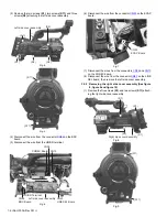
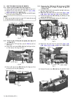
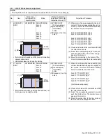
3.4.1 Removing the AUDIO board (See figure 15)
(1) Remove the right side cover assembly (Refer to the 3.2.2)
(2) Disconnect the wires from the connectors
CN10
,
CN44
,
CN45
and
CN62
on the AUDIO board.
(3) Remove the six screws
(S3)
attaching the AUDIO board,
then remove the AUDIO board.
Fig.15
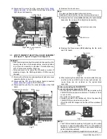
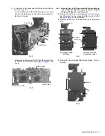
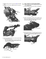
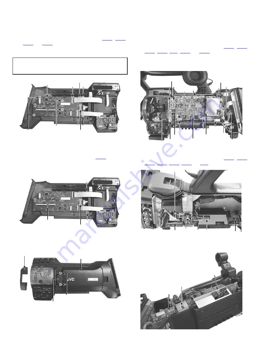
3.4.2 Removing the LCD monitor assembly (See figure 16
and figure 17)
(1) Disconnect the FPC from the connector
CN62
on the AU-
DIO board.
(2) Remove the two screws
(S12)
attaching the hinge unit cov-
er, then remove the hinge unit cover.
Fig.16
(3) Remove the two screws
(S9)
attaching the hinge unit, then
remove the LCD monitor assembly.
Fig.17
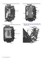
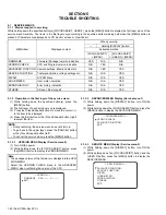
3.4.3 Removing the CAM board, SDI board and CODEC
board (See figure 18, figure 19, figure 20, figure 21
and figure 22)
(1) Remove the left side cover assembly and right side cover
assembly (Refer to the 3.2)
(2) Disconnect the wires from the connectors
CN26
,
CN27
,
CN28
,
CN90
,
CN8
,
CN29
and
CN30
on the CAM board.
(3) Remove the two screws
(S7)
attaching the SDI board, then
remove the SDI board.
(4) Remove the six screws
(S6)
attaching the CAM board.
Fig.18
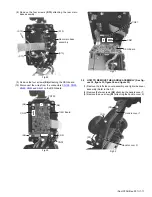
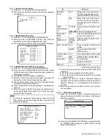
(5) Disconnect the wires from the connectors
CN58
,
CN57
,
CN22
,
CN67
,
CN12
,
CN88
and
CN9
on the CODEC board.
Fig.19
(6) Remove the two screws
(S6)
attaching the CODEC board.
Fig.20
NOTE :
CN62 may be slightly hard to connect FPC cable. Make sure
to insert the cable to correct position.
CN10
CN44
(S3)
(S3)
CN62
CN45
AUDIO Board
(S3)
(S3)
(S12)
(S12)
CN62
AUDIO Board
(S9)
Hinge unit
LCD Monitor assembly
Hinge unit cover
(S7)
(S6)
SDI
SDI
Board
Board
SDI
Board
CN30
CN29
(S6)
CN88
(S7)
(S6)
CAM Board
CN8
CN9
(S6)
CN28
(S6)
CN27
CN26
CN90 (S6)
CN67
CN12
CN58
CN22 CN57 CODEC Board
(S6)
(S6)
CODEC Board