


1-12 (No.HC034<Rev.001>)
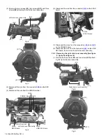
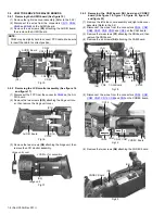
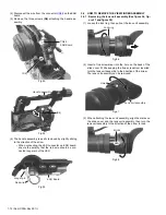
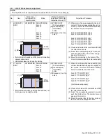
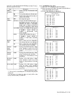
(4) Disconnect the wire from the connector
CN48
on the EAR
board.
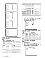
(5) Remove the three screws
(S4)
attaching the handle as-
sembly.
Fig.33
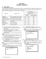
Fig.34
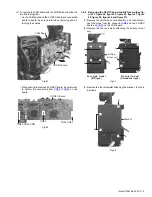
(6) The handle assembly is easily removed by slightly sliding
to the direction of the arrow.
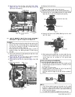
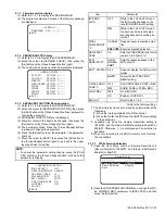
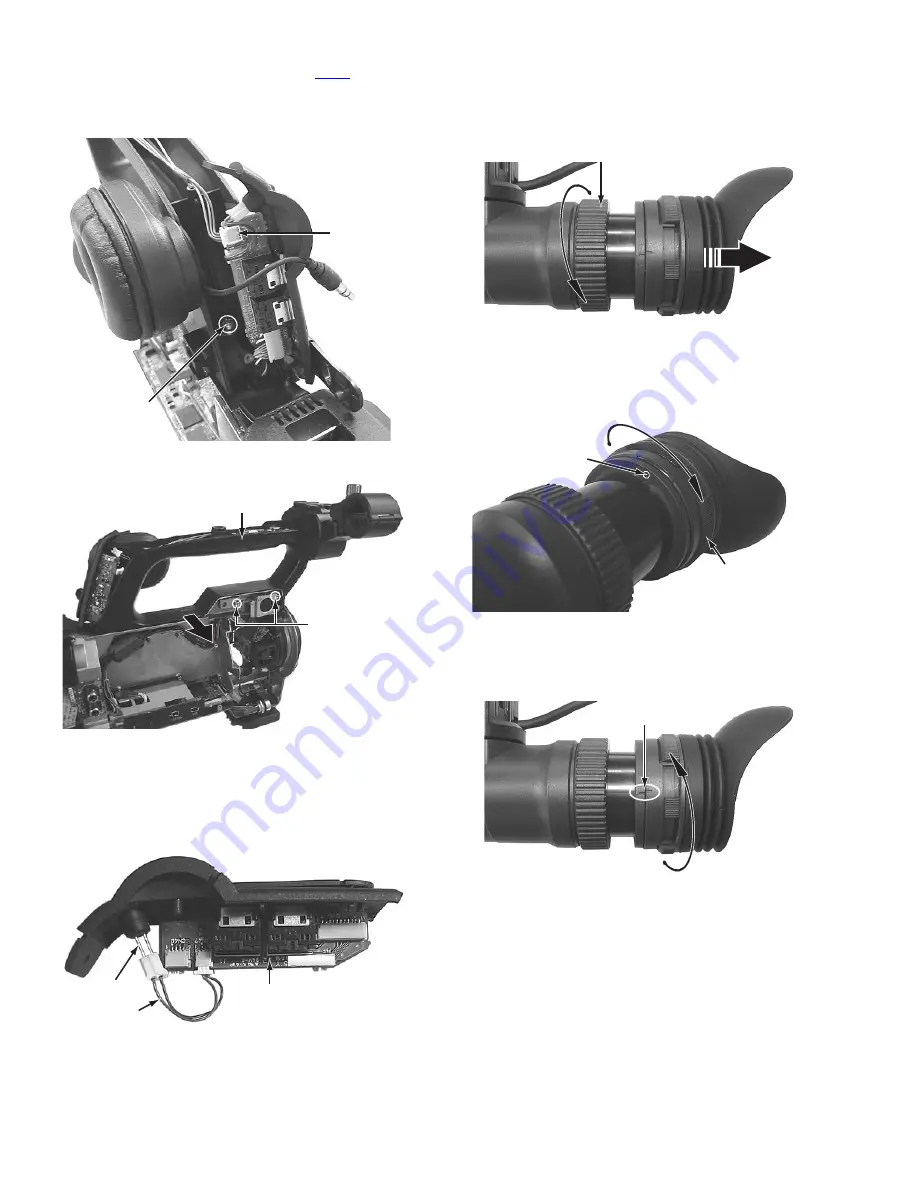
• When connecting the LED connector on EAR board,
ensure the polarity that the red wire should be con-
nected longer pin of the LED.
Fig.35
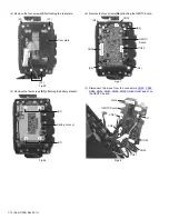
3.6
HOW TO REMOVE THE VIEW FINDER ASSEMBLY
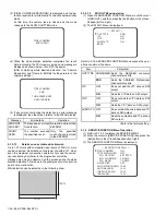
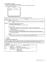
3.6.1 Removing the lens unit assembly (See figure 36, fig-
ure 37 and figure 38)
(1) Loosen the lock ring, then pull out the lens unit assembly.
Fig.36
(2) Insert a fine screwdriver into the hole on the back of the
slide cover. While keeping the fine screwdriver inserted,
turn the lens unit assembly to the direction of the arrow.
The lens unit assembly can be removed.
Fig.37
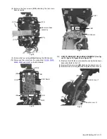
(3) When attaching the lens unit assembly, align the marks on
the slide cover and the lens unit assembly, then turn the
lens unit assembly to the direction of the arrow to lock.
Fig.38
(S4)
CN48
EAR Board
Handle assembly
(S4)
EAR Board
Red wire
Longer pin
Lock ring
Lens unit assembly
Hole
Marks