
1-30 (No.HC034<Rev.001>)
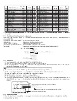
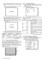
Check the defect of board or the connection of each board, if the "update error !" was displayed.
5.4
PRECAUTIONS WHEN CHANGING BOARDS
After changing the board in service, firmware version update and adjustment may be required.
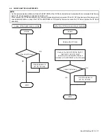
5.4.1 When version update is required
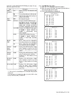
For GY-HM790, there are multiple CPUs and FPGAs allocated on the two boards. (Refer to the table below)
CPU/FPGA has its own firmware and each firmware has its combination.
When the CAM board assembly or the CODEC board assembly is replaced, the combination of versions may not match. In such case,
as camera could malfunction, make sure to perform version update after changing these boards.
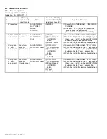
5.4.2 When adjustment is required
The adjustment data is stored in the EEP-ROM.
When the board to be changed is mounted with EEP-ROM, readjustment is required as the adjustment data will be lost.
Boards mounted with EEP-ROM are ISB Board (OP Block) and CODEC board. (Refer to section 5.2 EEP-ROM.)
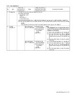
5.4.2.1
OPTICAL BLOCK ASSEMBLY (ISB BOARD)
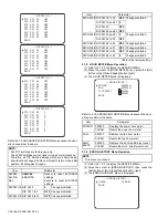
The EEP-ROM (IC10) of camera CPU, which stores CCD adjustment data and camera process data, is mounted in OPTICAL BLOCK
ASSEMBLY ISB Board.
OPTICAL BLOCK ASSEMBLY is supplied from the parts center after adjustment of CCD (Split Screen, Flare ADJ etc.) is completed.
By transferring the adjustment data of camera process after changing OP BLOCK ASSEMBLY, it is not required to readjust basically.
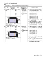
When the split screen appear on the monitor TV, confirm the 4.5.2 No.3 BLACK adjustment.
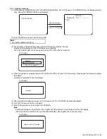
[How to transfer the adjustment data of camera process]
(1) Select the adjustment menu [201. EEP COPY SYS TO CAM] in the NTSC mode. (Refer to section 4.3 ADJUSTMENT MENU.)
(2) Press the [Set] button to start copying. The GY-HM790 reboots automatically. and the ADJUSTMENT MENU is displayed.
(3) Change the VIDEO MODE from NTSC to PAL, then execute the steps (1) to (2) in the same way.
5.4.2.2
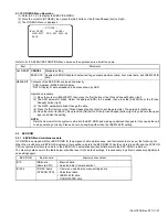
CODEC board Assembly
The adjustment data is stored in EEP-ROM IC1504. Adjustment is required after changing board.
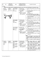
Update Error !
LCD display
Board assembly
CPU/FPGA with firmware
CAM Board assembly
IC37 (CAM CPU)
IC8 (Flash ROM for FPGA9)
IC12 (Flash ROM for FPGA8 and FPGA10)
CODEC Board assembly
IC1503 (SYS CPU)
IC3 (Flash ROM for FPGA11)
IC1006 (Flash ROM for MBE CPU)
NOTE :
The SYS CPU has the backup adjustment data of camera, and it's data is copied.
NOTE :
To continue using the EEP-ROM data, it is also possible to remount original IC1504 onto the new board.