


(No.HC034<Rev.001>)1-7
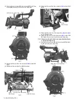
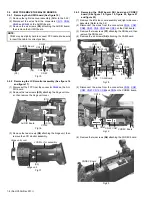
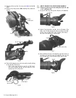
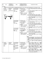
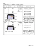
(2) Disconnect the wires from the connectors
CN14
,
CN24
,
CN43
and
CN11
on the AUDIO board, then remove the
right side cover assembly.
Fig.10
3.3
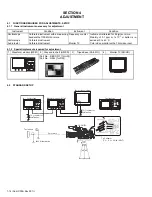
HOW TO REMOVE THE OPTICAL BLOCK ASSEMBLY
(See figure 11, figure 12, figure 13 and figure 14)
(1) Remove the left side cover assembly and right side cover
assembly (Refer to the 3.2)
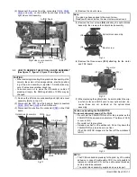
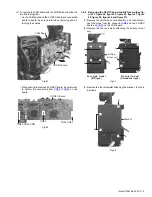
(2) Disconnect the FPC from the board to board connectors
CN26
,
CN27
and
CN28
on the CAM board.
(3) Disconnect the wire from the connector
CN90
on the CAM
board.
Fig.11
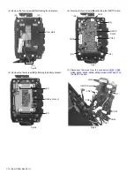
(4) Remove the mount screw.
(5) Remove the four screws
(S8)
attaching the optical block
assembly, then remove the optical block assembly.
Fig.12
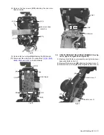
(6) Remove the three screws
(S12)
attaching the fan motor
and FNC board.
Fig.13
(7) When replacing the optical block, be sure to attach the orig-
inal fan motor and FNC board to new optical block, be-
cause those are not included on the optical block
assembly.
Fig.14
CAUTION :
• When removing/mounting the optical block assembly in the
camera, take care not to damage cables, also the position-
ing of the wire assembly is important. A malfunction may
occur if wires are somehow caught up.
• Take also care not to press the IS boards or cables. If
pressing strongly, the RGB registration of CCDs may be
changed.
AUDIO Board
Right side cover assembly
CN24
CN11
CN14
CN43
Optical block assembly
CN90
CN28
CN26
CAM Board
CN27
Note:
The glue has been applied to the mount screw.
Replace with new one when the mount screw was removed.
Caution on handling the FAN MOTOR
To prevent abnormal sound of the FAN:
• Do not hold the FAN MOTOR shaft or the propeller as the
FAN MOTOR has a precision structure. (The force of 0.3 N
or over is NG.)
• Be careful not to give shock.
• Spread a cushion on the workbench. Do not lay down the
FAN MOTOR on a hard board or a floor.
(The FAN MOTOR dropped to the floor off the workbench
is NG.)
NOTE :
• The CCDs are bonded precisely to the prism by UV-curable
adhesive. In case of trouble with a CCD, it is not possible to
replace an individual CCD, but the entire optical block as-
sembly should be replaced.
• The optical block assembly supplied as a service part.
Optical block assembly
(S8)
(S8)
Mount screw
FNC Board
(S12)
(S12)
Fan motor