


(No.HC034<Rev.001>)1-5
SECTION 2
SPECIFIC SERVICE INSTRUCTIONS
This service manual does not describe SPECIFIC SERVICE INSTRUCTIONS.
SECTION 3
DISASSEMBLY
About CH model : CH models are without only lens assem-
bly.
3.1
GENERAL DESCRIPTION
3.1.1 Cautions
(1) Always unplug the DC power or the battery before attach-
ing, removing or soldering a part.
(2) When unplugging a connector, do not pull the wire but
grasp the connector body.
(3) When attaching exterior cover, put the cables and wire in
order and check carefully not to damage cables.
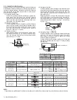
3.1.2 Screws used in camera components
The table is shows the symbols, design, part numbers and colors
of screws used with the camera components.
When disassembling or assembling the camera, be sure to install
the correct screws by referring to the following table.
3.2
HOW TO REMOVE THE EXTERIOR PARTS
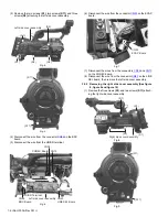
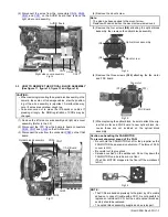
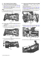
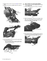
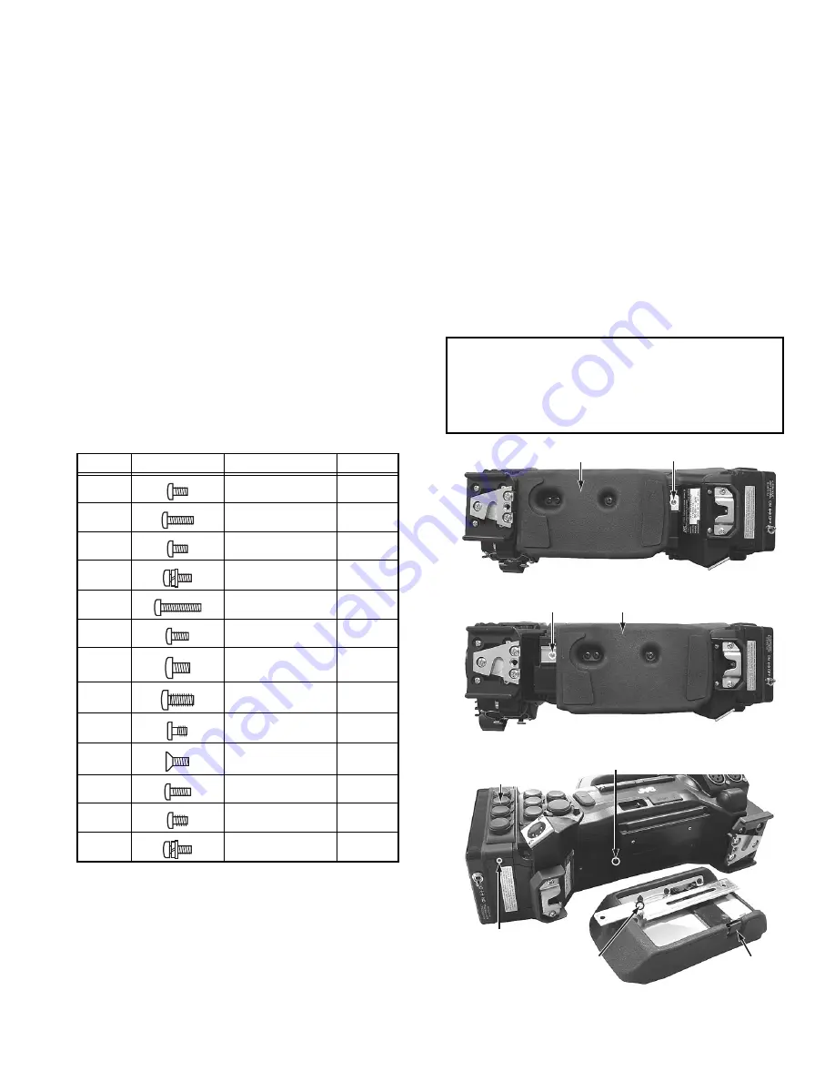
3.2.1 Removing the left side cover assembly (See figure 1,
figure 2, figure 3, figure 4, figure 5, figure 6 and figure
7)
(1) Remove the two screws
(S10)
attaching the shoulder pad,
then remove the shoulder pad.
(2) Remove the one screw
(S1)
attaching the CN cover as-
sembly.
Fig.1
Fig.2
Fig.3
Symbol
Design
Part No.
Color
(S1)
QYSPSPU2040MA Black
(S2)
QYSPSPU2080MA Black
(S3)
QYSPSPU2030NA Silver
(S4)
QYSPSPH4012NA Silver
(S5)
QYSPSPU2080MA Black
(S6)
QYSPSPU2040NA Silver
(S7)
QYSDSP2605NA
Silver
(S8)
QYSDSP3008MA
Black
(S9)
LY30031-052A
Black
(S10)
QYSSSP2606NA
Silver
(S11)
QYSPSPU2060MA Black
(S12)
QYSPSFU2040MA Black
(S13)
QYSPSPH3008NA Silver
NOTE :
• When attaching the shoulder pad, make sure to insert the
guide rail of the shoulder pad into the hole of the bottom
and tighten the screws.
• When attaching the shoulder pad, pressing the push plate
and then slide the guide rail.
Shoulder pad
(S10)
Shoulder pad
(S10)
Push plate
Hole
(S1)
CN Cover assembly
Guide rail