


(No.HC034<Rev.001>)1-11
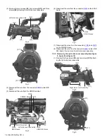
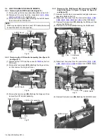
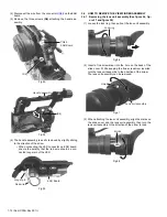
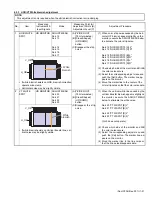
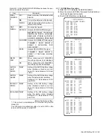
(8) Remove the four screws
(S13)
attaching the rear main
base assembly.
Fig.29
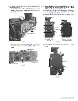
(9) Remove the four screws
(S6)
attaching the REG board.
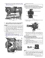
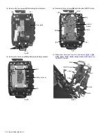
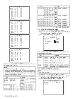
(10) Disconnect the wires from the connectors
CN109
,
CN30
,
CN32
,
CN91
and
CN31
on the REG board.
Fig.30
Fig.31
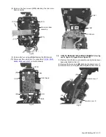
3.5
HOW TO REMOVE THE HANDLE ASSEMBLY (See fig-
ure 32, figure 33, figure 34 and figure 35)
(1) Remove the left side cover assembly and right side cover
assembly (Refer to the 3.2)
(2) Remove the two screws
(S5)
attaching the handle cover T.
(3) Remove the one screw
(S1)
attaching the handle cover R.
Fig.32
(S13)
(S13)
(S13)
(S13)
Rear main base
assembly
(S6)
CN30
(S6)
REG Board
CN109
(S6)
(S6)
CN32
CN31
REG Board
CN91
(S5)
(S5)
(S1)
Handle cover T
Handle cover R