background image

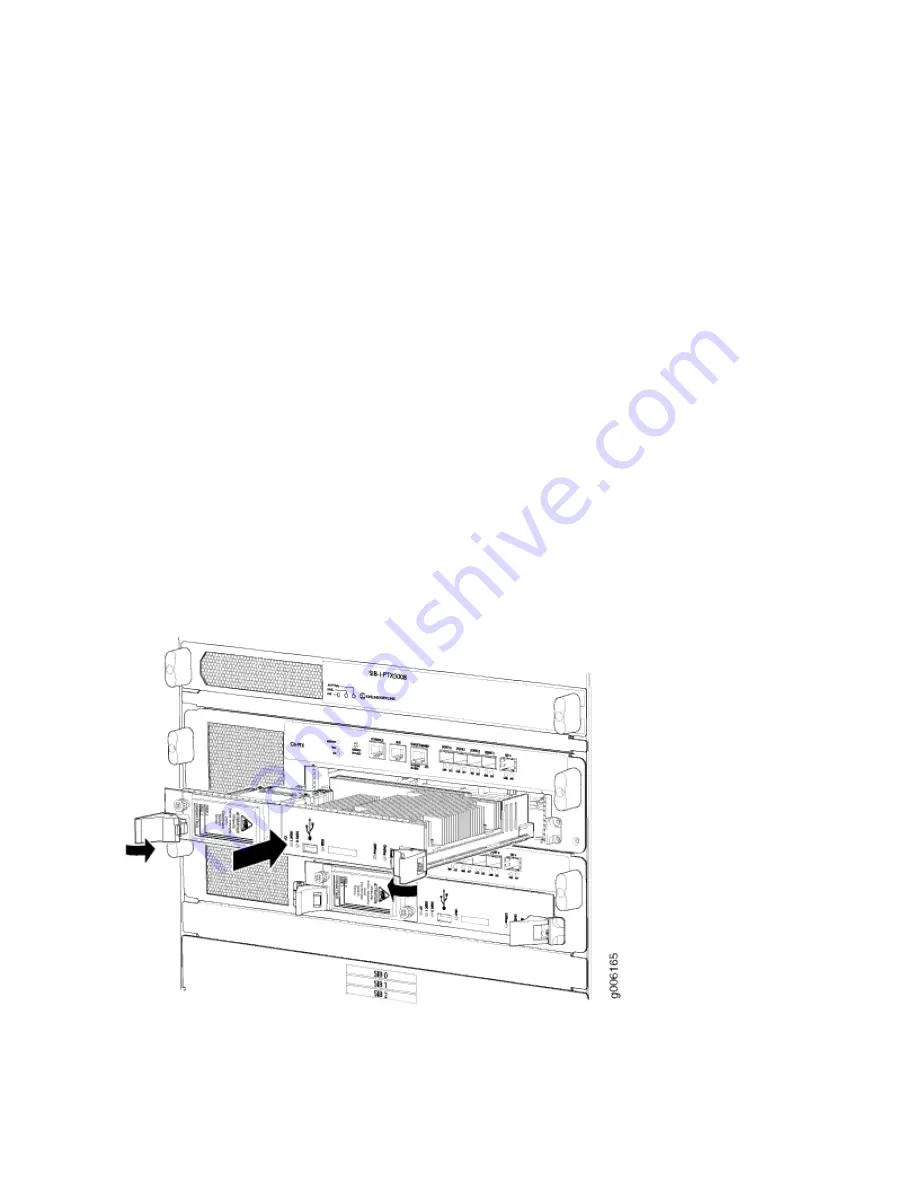
1. Attach an electrostatic discharge (ESD) grounding strap to your bare wrist, and connect the strap to

one of the ESD points on the chassis.

2. Ensure that the ejector handles are not in the locked position. If necessary, press the red tabs and flip

the ejector handles outward.

3. Place one hand underneath the Routing Engine to support it. With the other hand, grasp one of the

ejector handles on the faceplate.

4. Carefully align the sides of the Routing Engine with the guides inside the opening on the Control

Board.

5. Slide the Routing Engine into the chassis until you feel resistance, then press the Routing Engine's

faceplate until it engages the connectors.

6. Press both the ejector handles inward to seat the Routing Engine.

The Routing Engine might require several minutes to boot. If the PTX5000 is powered on and the
Routing Engine's corresponding Control Board is functioning normally, the Routing Engine comes
online automatically.

7. Verify that the Routing Engine is installed correctly and functioning properly:

• Verify that the green ONLINE LED lights steadily.

• Verify the status of the Routing Engine using the show chassis routing-engine command.

Figure 248: Installing a Routing Engine

468

Содержание PTX5000

Страница 1: ...PTX5000 Packet Transport Router Hardware Guide Published 2022 12 04...

Страница 2: ...rdware Guide Copyright 2022 Juniper Networks Inc All rights reserved The information in this document is current as of the date on the title page YEAR 2000 NOTICE Juniper Networks hardware and softwar...

Страница 3: ...ription 14 PTX5000 Midplane Description 18 PTX5000 Cable Management System 18 PTX5000 Craft Interface Description 19 PTX5000 Craft Interface LEDs 23 PTX5000 Centralized Clock Generator Description 29...

Страница 4: ...Ds 105 PTX5000 DC Power System Electrical Specifications 109 PTX5000 DC Power Distribution Unit Specifications 110 PTX5000 DC Power Cable and Lugs Specifications 111 PTX5000 DC Power Distribution 114...

Страница 5: ...fications 169 Site Electrical Wiring Guidelines 173 Rack Requirements for the PTX5000 174 PTX5000 Power Planning 177 Calculating PTX5000 Power Consumption 177 Power Requirements for PTX5000 Components...

Страница 6: ...ived 203 Installing the PTX5000 in a Rack 206 Installing the PTX5000 Mounting Hardware for a Four Post Rack or Cabinet 206 Installing Cage Nuts If Needed 206 Installing the Four Post Mounting Shelf an...

Страница 7: ...ment Comb Assembly Extension 260 Installing the Cable Management Comb Assembly Without Extension 261 Connecting Power to the PTX5000 60 A DC Input Power Trays 262 Connecting Power to the PTX5000 120 A...

Страница 8: ...TX5000 303 Entering Configuration Mode 304 Configuring User Accounts and Passwords 304 Configuring System Attributes 305 Committing the Configuration 306 4 Maintaining Components Maintaining the PTX50...

Страница 9: ...alling a PTX5000 Horizontal Air Filter 332 Replacing a PTX5000 Vertical Air Filter 335 Removing a PTX5000 Vertical Air Filter 335 Installing a PTX5000 Vertical Air Filter 337 Replacing a PTX5000 Power...

Страница 10: ...Capacity Delta AC PDU 390 Replacing a PTX5000 High Capacity Wye AC PDU 394 Removing a PTX5000 High Capacity Wye AC PDU 394 Installing a PTX5000 High Capacity Wye AC PDU 398 Replacing a PTX5000 High C...

Страница 11: ...nstalling a PTX5000 High Capacity DC PSM 448 Upgrading the PTX5000 to a High Capacity Power System 449 Upgrading to the High Capacity AC Power System 449 Upgrading to the High Capacity DC Power System...

Страница 12: ...ment Console or Auxiliary Port Cable 489 Removing a Management Console or Auxiliary Port Cable 489 Installing a Management Console or Auxiliary Port Cable 490 Replacing a PTX5000 Management Ethernet C...

Страница 13: ...tch Interface Board 507 Installing a PTX5000 Switch Interface Board 508 Maintaining PTX5000 Interface Modules 509 Maintaining the PTX5000 FPCs 509 Holding PTX5000 FPCs 510 Preventing Damage to FPCs 51...

Страница 14: ...rational PTX5000 547 Upgrading to the High Capacity Power System 547 Upgrading the Horizontal Fan Tray 547 Removing and Replacing SIBs in an Operational PTX5000 547 Upgrading the FPCs in an Operationa...

Страница 15: ...TX5000 FPCs 620 Troubleshooting the PTX5000 PICs and PIC Transceivers 625 Troubleshooting PTX5000 PICs 625 Troubleshooting PTX5000 PIC Transceivers 628 6 Returning the Chassis or Components Returning...

Страница 16: ...s 685 PTX5000 Agency Approvals 685 Compliance Statements for EMC Requirements 686 Compliance Statements for Environmental Requirements 688 PTX5000 Compliance Statements for NEBS 688 PTX5000 Compliance...

Страница 17: ...Requirements and Warning 698 DC Power Wiring Sequence Warning 699 DC Power Wiring Terminations Warning 701 Midplane Energy Hazard Warning 702 Multiple Power Supplies Disconnection Warning 702 TN Powe...

Страница 18: ...roubleshooting for the PTX5000 Packet Transport Router After completing the installation and basic configuration procedures covered in this guide refer to the Junos OS documentation for information ab...

Страница 19: ...PTX5000 System Overview 2 PTX5000 Chassis 13 PTX5000 Cooling System 32 PTX5000 AC Power System 38 PTX5000 DC Power System 86 PTX5000 Host Subsystem 116 PTX5000 Switch Interface Boards 139 PTX5000 Int...

Страница 20: ...and network applications such as those supported by ISPs and high volume content providers Benefits of the PTX5000 Router Increased scalability The PTX5000 scales to 24 Tbps in a single chassis suppo...

Страница 21: ...n be configured with two Physical Interface Cards PICs to support a variety of network media types The system architecture of the PTX5000 cleanly separates control operations from packet forwarding op...

Страница 22: ...ront and rear of a PTX5000 and its components Figure 1 Front View of the PTX5000 1 Front mounting flange 6 FPCs and PICs 2 Craft interface 7 ESD point 3 Upper horizontal fan tray 8 Lower horizontal fa...

Страница 23: ...supply module door and power supply modules air filter Figure 2 Rear View of the PTX5000 1 Center mounting bracket 6 Control Board CB1 and Routing Engine RE1 2 Air exhaust 7 ESD point 3 Centralized Cl...

Страница 24: ...g Engines perform their primary tasks independently but communicate through multiple links This arrangement streamlines forwarding and routing control and runs Internet scale backbone networks at high...

Страница 25: ...ble 1 PTX5000 Hardware Components Component Model Number Hardware Label CLI Output Description Cable management system PTX5000 Cable Management System on page 18 Centralized Clock Generator CCG CCG PT...

Страница 26: ...s required for maintenance See Maintaining the PTX5000 Air Filters on page 329 FLTR PTX KIT Control Board CB PTX CB PTX Control Board PTX5000 Control Board Description on page 131 CB2 PTX CB2 PTX Cont...

Страница 27: ...Board 2 RE DUO C2600 16G RE DUO 2600 RE PTX X8 64G RE PTX X8 64G RE PTX 2X00x8 Midplane Midplane 8S PTX5000 Midplane Description on page 18 Midplane 8SeP PIC See the PTX Series Interface Module Refere...

Страница 28: ...DC 12V Power Supply 60 A DC PSM PSM PTX DC 60 DC 12V PSM 2x60A High Capacity DC PSM PSM2 PTX DC High Capacity DC PSM PSM blank PSM BLANK PTX High Capacity Single Phase AC PDU PDU2 PTX AC SP PDU2 PTX...

Страница 29: ...sists of a Routing Engine functioning together with a Control Board To operate each host subsystem requires a Routing Engine installed in a slot in the Control Board The PTX5000 can have one or two ho...

Страница 30: ...tages to PTX5000 components depending on their voltage requirements The number of PSMs required for full redundancy varies depending on the configuration of the chassis NOTE The normal capacity power...

Страница 31: ...er SIBs are operational Backup Control Boards Primary Control Boards if nonstop active routing is configured Backup Routing Engines Primary Routing Engines if nonstop active routing is configured SIBs...

Страница 32: ...includes the following features see Figure 3 on page 15 and Figure 4 on page 16 Front mounting flanges for mounting in a four post rack or cabinet Center mounting metal brackets for center mounting in...

Страница 33: ...be connected to earth ground during normal operation Figure 3 Front View of the PTX5000 Chassis 1 Front mounting flange 6 FPCs and PICs 2 Craft interface 7 ESD point 3 Upper horizontal fan tray 8 Lowe...

Страница 34: ...5 Vertical fan tray and vertical air filter 10 Power supply module door and power supply modules air filter Figure 4 Rear View of the PTX5000 Chassis 1 Center mounting bracket 6 Control Board CB1 and...

Страница 35: ...itch Interface Boards SIBs 9 Chassis grounding points 5 Control Board CB0 and Routing Engine RE0 Figure 5 ESD Points on the PTX5000 SEE ALSO PTX5000 Description 2 PTX5000 Component Redundancy 11 PTX50...

Страница 36: ...gnal path The midplane provides the signal path to the FPCs SIBs Routing Engines Control Boards and other system components for monitoring and control of the system NOTE The PTX5000 supports two midpl...

Страница 37: ...ou use the cable management system to maintain the cable bend radius SEE ALSO Maintaining the PTX5000 PIC Cables 527 PTX5000 Craft Interface Description IN THIS SECTION Craft Interface Front Panel 20...

Страница 38: ...s 4 CCG LEDs 9 LCD 5 Fan tray LEDs 10 LCD navigation buttons The front panel of the craft interface contains A four line LCD display along with six navigation buttons The LCD display operates in Idle...

Страница 39: ...ace along with six navigation buttons The LCD operates in two modes LCD idle mode LCD alarm mode Idle Mode During normal operation the LCD operates in idle mode and reports current status information...

Страница 40: ...alarm mode and reports the alarm condition as shown in Figure 8 on page 22 Figure 8 LCD in Alarm Mode The lines in the display report the following information First line Router name Second line Numb...

Страница 41: ...e Host Subsystem LEDs 25 CCG LEDs 26 Fan Trays LEDs 26 Power Distribution Unit LEDs 27 Power Supply Modules LEDs 27 Figure 9 on page 23 shows the craft interface LEDs Figure 9 Craft Interface LEDs 1 S...

Страница 42: ...5000 Craft Interface Shape Color State Description Red On steadily Critical alarm LED Indicates a critical condition that can cause the PTX5000 to stop functioning Possible causes include component re...

Страница 43: ...EDs listed under HOST0 show the status of the Routing Engine in slot RE0 and the CB in slot CB0 The LEDs listed under HOST1 show the status of the Routing Engine in slot RE1 and the CB in slot CB1 Tab...

Страница 44: ...escription MASTER Green On steadily CCG is functioning as the primary Off CCG is offline or functioning as the backup OK Green On steadily CCG is online and is functioning normally Off CCG is offline...

Страница 45: ...8 Power Distribution Unit LEDs Colour State Description Green On steadily PDU is functioning normally Red On steadily PDU has failed Off PDU might be starting up or not receiving any input voltage Th...

Страница 46: ...PSMs 0 and 4 PSMs 1 and 5 PSMs 2 and 6 PSMs 3 and 7 Table 10 Power Supply Module LEDs on the Craft Interface Color State Description for normal capacity PDU PSMs Description for high capacity PDU PSMs...

Страница 47: ...t CCG is hot pluggable For redundant CCGs the primary CCG is hot pluggable The backup CCG is hot removable and hot insertable if the primary CCG is functioning Removing the backup CCG does not affect...

Страница 48: ...orts 2 ONLINE OFFLINE button 4 Four GPS connectors labeled GPS0 CLOCK GPS0 SYNC GPS1 CLOCK and GPS1 SYNC for GPS external clock inputs 5 MHz or 10 MHz The LEDs for the GPS ports are not supported SEE...

Страница 49: ...he backup or is not powered on Table 12 CCG Port LEDs Label Color State Description LINK NOTE The LINK LEDs are supported only for the BITS ports This LED is not supported for the GPS ports Green On s...

Страница 50: ...ed the Routing Engine shuts down some or all of the hardware components If a fan fails or the temperature rises above the temperature thresholds the speed of the remaining fans in the zone is automati...

Страница 51: ...The upper Fan Tray 1 and lower Fan Tray 2 horizontal fan trays each of which contain six fans cool the components installed in the front card cage FPCs and PICs and the CCGs Both horizontal fan trays...

Страница 52: ...o FPCs are installed in cooling zone 1 section 1 the left fans in the horizontal fan trays in cooling zone 1 are set to 34 of maximum speed When no FPCs are installed in cooling zone 1 section 2 the r...

Страница 53: ...Airflow Figure 14 on page 35 shows the airflow through the PTX5000 Figure 14 Airflow Through the Chassis Air Filters The cooling system contains three air filters 35...

Страница 54: ...One air filter is located inside the vertical fan tray Figure 15 on page 36 Figure 15 Vertical Fan Tray Air Filter 36...

Страница 55: ...al fan tray Figure 16 on page 37 Figure 16 Horizontal Fan Tray Air Filter One air filter is located inside the door for the power supply modules Figure 17 on page 37 Figure 17 PSM Door Air Filter All...

Страница 56: ...N PTX5000 AC Power System Description 39 PTX5000 AC Power Distribution Unit LEDs 58 PTX5000 AC Power Supply Module LEDs 70 PTX5000 AC Power System Specifications 73 PTX5000 Three Phase Delta AC Power...

Страница 57: ...apacity AC PSM 56 PTX5000 High Capacity AC PSM 57 AC PDUs Supported on the PTX5000 The PTX5000 supports the AC PDUs in Table 13 on page 39 NOTE Ensure that you use AC PDUs of the same model number dur...

Страница 58: ...input terminal block and ground The AC terminal block consists of three input terminals labeled L1 L2 and L3 One 60 A circuit breaker A power OUTPUT switch that provides power to the PSMs LEDs to moni...

Страница 59: ...NOTE The PDUs contain no fans but are cooled by the fans in the power supply modules 41...

Страница 60: ...Figure 18 Three Phase Delta AC PDU 1 Top Installation handle 5 Circuit breaker 2 Front installation handle 6 Wiring compartment 3 Power OUTPUT switch 7 Wiring compartment door 42...

Страница 61: ...ta AC power cord Normal Capacity Three Phase Wye AC PDU Components Each normal capacity three phase wye AC PDU has the following components Figure 20 on page 46 A metal bracket located on the lower ri...

Страница 62: ...nty one monitored electronic fuses for the fan trays Control Boards and FPCs NOTE There are no mechanical fuses in the PDU to be replaced For output voltage current protection is provided by electroni...

Страница 63: ...NOTE The PDUs contain no fans but are cooled by the fans in the power supply modules 45...

Страница 64: ...Figure 20 Three Phase Wye AC PDU 1 Top Installation handle 5 Circuit breaker 2 Front installation handle 6 Wiring compartment 3 Power OUTPUT switch 7 Wiring compartment door 46...

Страница 65: ...1 Retaining nut 2 Three phase wye AC power cord PTX5000 High Capacity Delta and Wye AC PDU The High Capacity AC Delta and Wye AC PDUs support the following features Up to eight PSMs are installed for...

Страница 66: ...acity Delta AC PDU has the following components see Figure 22 on page 49 A metal retaining bracket located on the lower right to connect the delta AC power cord to the PDU A metal wiring compartment t...

Страница 67: ...upply modules Figure 22 High Capacity Delta AC PDU 1 Top installation handle 6 Input voltage LED 2 Front installation handle 7 Wiring compartment 3 PDU OK LED 8 Power input cord selection switch 4 Pow...

Страница 68: ...er cord The High Capacity Delta AC PDU supports three power cords for 60 A 100 A and 150 A See Connecting Power to the PTX5000 High Capacity Delta AC PDUs on page 235 for setting the power cord select...

Страница 69: ...tment that contains the AC input terminal block and ground The AC terminal block consists of three input terminals labeled L1 L2 and L3 from left to right The neutral input is labeled N One 80 A circu...

Страница 70: ...he power supply modules Figure 24 High Capacity Wye AC PDU 1 Top installation handle 6 Circuit breaker 2 Front installation handle 7 Input voltage LED 3 PDU OK LED 8 Wiring compartment 4 Power switch...

Страница 71: ...ventilation 10 Wiring compartment door Each High Capacity Wye AC PDU weighs approximately 63 3 lb 28 7 kg Figure 25 on page 53 shows the power cord for the High Capacity Wye AC PDU Figure 25 AC Power...

Страница 72: ...ket to cover 20 A or 30 A connectionswith an built in switch to indicate to the system which connectionsare active 20 A or 30 A inputs 30 4 KW output power with eight 30 A inputs or 23 KWoutput power...

Страница 73: ...apacity Single PhaseAC PDU Components 1 PDU OK LED 3 20 A 30 A Power cord input connectors 2 Output Enable switch 4 PSM LEDs Each High Capacity Single Phase AC PDU has the following components Figure...

Страница 74: ...operation Table 14 AC PSMs Supported on the PTX5000 Name Model Number First Supported Junos OS Release AC PSM PSM PTX AC 12 3 High Capacity AC PSM PSM2 PTX AC 14 2 PTX5000 Normal Capacity AC PSM Figur...

Страница 75: ...AC PSM before installing it in any high capacity AC PDU Figure 27 AC PSM PTX5000 High Capacity AC PSM Figure 28 on page 58 shows the High Capacity AC PSM These PSMs are smaller than the normal capaci...

Страница 76: ...and might show very low or zero output current Light load condition occurs when the average input power to the PSMs is less than 422 W Figure 28 High Capacity AC PSM PTX5000 AC Power Distribution Unit...

Страница 77: ...High Capacity Delta AC PDU LEDs 66 High Capacity Wye AC PDU 68 59...

Страница 78: ...Three Phase Delta AC PDU LEDs Figure 29 on page 61 shows the three phase delta AC PDU LEDs 60...

Страница 79: ...Figure 29 Three Phase Delta AC PDU LEDs 1 PDU OK LED 3 200 240 V 60 A 50 60 Hz LED 2 CB ON LED Table 15 on page 62 describes the LEDs on the three phase delta AC PDU faceplate 61...

Страница 80: ...s starting up 200 240 V 60 A 50 60 Hz Green On steadily Input is receiving voltage Off Input voltage is not present or is under 100 VAC CB ON Green On steadily Circuit breaker is powered on Off This L...

Страница 81: ...Three Phase Wye AC PDU LEDs Figure 30 on page 64 shows the three phase wye AC PDU LEDs 63...

Страница 82: ...Figure 30 Three Phase Wye AC PDU LEDs 1 PDU OK LED 3 220 240 V 346 415 V 30 A 50 60 Hz LED 2 CB ON LED Table 16 on page 65 describes LEDs on the the three phase wye AC PDU faceplate 64...

Страница 83: ...ng up 220 240 V 346 415 V 30 A 50 60 Hz Green On steadily PDU is receiving AC voltage Off AC input voltage is not present or is under 100 VAC CB ON Green On steadily Circuit breaker is powered on Off...

Страница 84: ...U LEDs Figure 31 High Capacity Delta AC PDU LEDs 1 PDU OK LED 2 AC input LED Table 17 on page 66 describes the LEDs on the High Capacity Delta AC PDU faceplate Table 17 High Capacity Delta AC PDU LEDs...

Страница 85: ...occurred but the 36 V output remains operational Red On steadily PDU has failed Off This LED can be off for one of the following reasons The PDU is not receiving any input voltage The PDU is starting...

Страница 86: ...Figure 32 High Capacity Wye AC PDU LEDs 1 PDU OK LED 3 AC input LED 2 CB OK LED Table 18 on page 68 describes the LEDs on the High Capacity Wye AC PDU faceplate Table 18 High Capacity Wye AC PDU LEDs...

Страница 87: ...The PDU is starting up CB OK Green On steadily Circuit breaker is powered on Off This LED can be off for one of the following reasons Circuit breaker is not powered on The circuit breaker might have b...

Страница 88: ...EDs IN THIS SECTION AC Power Supply Module LEDs 70 High Capacity AC Power Supply Module LEDs 71 AC Power Supply Module LEDs Figure 33 on page 70 describes the LEDs on the AC power supply module PSM fa...

Страница 89: ...inking PSM is not enabled or is in a fault condition or the input voltage to the PSM is too low Off Output is not functioning normally because of a fault condition or the PSM is not receiving input vo...

Страница 90: ...resent AC outputOK Green On steadily Output is functioning normally and input voltage is within the supported range Blinking PSM is not enabled or is in a fault condition or the input voltage to the P...

Страница 91: ...ecifications Table 21 AC Power System Electrical Specifications Item Specification AC input voltage Delta operating range 200 through 240 VAC line to line nominal Wye operating range 200 through 240 V...

Страница 92: ...y 50 60 Hz nominal AC input current rating 40 A 240 VAC line to line 48 A 200 VAC line to line Maximum AC input 16 600 W PTX5000 Three Phase Wye AC Power Distribution Unit Specifications Table 23 on p...

Страница 93: ...ectrical specifications Table 24 High Capacity Delta AC PDU Electrical Specifications Item Specification Maximum output power 30 400 W AC input voltage Operating range 200 through 277 VAC line to line...

Страница 94: ...line nominal AC input line frequency 50 60 Hz nominal AC input current rating For the 63 A power cord the maximum input current is 58 A 220 VAC PTX5000 High Capacity Single Phase AC Power Distribution...

Страница 95: ...aphical location NOTE In North America AC power cords must not exceed 4 5 m approximately 14 8 ft in length to comply with National Electrical Code NEC Sections 400 8 NFPA 75 5 2 2 and 210 52 and Cana...

Страница 96: ...ords Continued Power Cord Region Model Number Electrical Specification Plug Type Wire Pole CBL2 PTX 100AC D 100 A 250 V CBL2 PTX 150AC D 150 A 250 A Wye Europe CBL PTX AC W 32 A 400 VAC IEC60309 5 wir...

Страница 97: ...Figure 34 on page 79 and Figure 35 on page 80 show the AC power cord provided for each region supported Figure 34 Three Phase Delta AC Power Cord 79...

Страница 98: ...1 Retaining nut 2 Three phase delta AC power cord Figure 35 Three Phase Wye AC Power Cord 1 Retaining nut 2 Three phase wye AC power cord 80...

Страница 99: ...e 36 on page 81 through Figure 40 on page 83 show the three phase plugs for each region Figure 36 Three Phase Delta 60 A Plug Type North America Figure 37 Three Phase Delta 100 A Plug Type North Ameri...

Страница 100: ...Figure 38 Three Phase Delta 150 A Plug Type North America Figure 39 Three Phase Wye 32 A Plug Type Europe 82...

Страница 101: ...mponents or drape where people could trip on them Table 28 on page 83 provides specifications for the high capacity single phase AC power cords Table 28 AC Power Cord Specifications for the High Capac...

Страница 102: ...93 SABS 164 3 South Africa India Straight Plug to Straight C19 CBL2 PTX SP AU Australia AS NZS 3112 Type I Australia Straight Plug to Straight C19 CBL2 PTX SP US L L6 20 NEMA L6 20 US Canada Straight...

Страница 103: ...DOCUMENTATION Understanding Normal Capacity Power System Power Zones 182 Calculating PTX5000 Power Consumption 177 Connecting the PTX5000 to AC Power 221 Powering the PTX5000 On and Off 291 Maintaini...

Страница 104: ...pecifications 109 PTX5000 DC Power Distribution Unit Specifications 110 PTX5000 DC Power Cable and Lugs Specifications 111 PTX5000 DC Power Distribution 114 PTX5000 DC Power System Description IN THIS...

Страница 105: ...s OS Release DC PDU 120 A feeds PDU PTX DC 120 12 1X48 12 3 DC PDU 60 A feeds PDU PTX DC 60 12 1X48R3 12 3 High Capacity DC PDU 60 A feeds PDU2 PTX DC 14 1 PTX5000 Normal Capacity DC PDU Normal Capaci...

Страница 106: ...43 60 A DC PDU 1 Metal handle 4 Input power switches 2 Power OUTPUT switch 5 Input power trays 3 Air exhaust ventilation Each 60 A DC PDU has the following components Four removable input power trays...

Страница 107: ...ut is labeled RTN and 48 V The input power switch for both inputs in each input power tray is located on the PDU above the input power tray Figure 44 60 A DC Input Terminals LEDs to monitor the status...

Страница 108: ...t voltage current protection is provided by electronic fuses hot swap circuits or ORing circuit Electronic fuses and hot swap circuits also provide current limitation NOTE The PDUs contain no fans but...

Страница 109: ...on page 91 shows the 120 A DC PDU Each 120 A DC PDU weighs approximately 60 lb 27 2 kg Figure 45 120 A DC PDU 1 Metal handle 4 Circuit breakers 2 Power switch 5 Input power trays 3 Air exhaust ventil...

Страница 110: ...s contain no fans but are cooled by the fans in the power supply modules High Capacity DC PDU Description The High Capacity DC PDU 60 A provides 30 4 kW power output and you can connect a maximum of e...

Страница 111: ...sables the outputs from all the PSMs in the PDU Reverse polarity protection The PDU or PSMs are not damaged even if the input voltage is reversed for an indefinite period of time Hot pluggable and hot...

Страница 112: ...A DC PDU Each 60 A DC PDU weighs approximately 64 5 lb 29 3 kg Figure 46 High Capacity DC PDU 1 Metal handle 4 PSM LEDs 2 PDU OK LED 5 Input power terminals and safety cover 3 Power switch Each High...

Страница 113: ...rtically Each terminal has inputs for each PSM for example PSM0_1 indicates the first input terminal for PSM0 Each input is also labeled RTN and 48 V 60A see Figure 47 on page 95 and Figure 48 on page...

Страница 114: ...o monitor the status of the PDU See PTX5000 DC Power Distribution Unit LEDs on page 99 for details Air exhaust ventilation PTX5000 DC Power Supply Module DC PSMs Supported on the PTX5000 The PTX5000 s...

Страница 115: ...M2 PTX DC 14 1 PTX5000 Normal Capacity DC PSM Figure 49 on page 98 shows both the normal capacity 60 A DC PSM and 120 A DC PSM Each DC PSM weighs approximately 10 6 lb 4 8 kg CAUTION The 60 A DC PSM a...

Страница 116: ...tput and accepts two 60 A input feeds These PSMs are smaller than the 60 A DC and 120 A DC PSMs allowing up to eight PSMs to be installed per PDU and up to 16 PSMs per chassis The following is a list...

Страница 117: ...I2C fault reporting and control Figure 50 on page 99 shows the High Capacity DC PSM Figure 50 High Capacity DC PSM PTX5000 DC Power Distribution Unit LEDs IN THIS SECTION 60 A DC PDU LEDs 100 120 A D...

Страница 118: ...s Figure 51 60 A DC PDU 1 PDU OK LED 3 DC IN LEDs 2 SW ON LEDs Table 31 on page 100 describes the LEDs on the 60 A DC PDU faceplate Table 31 60 A DC PDU LEDs LED Color State Description PDU OK One per...

Страница 119: ...e Off Input voltage is not present or is under 40 V SW ON One per input power tray Green On steadily The input power switch is powered on Off The LED might be off for one of the following reasons The...

Страница 120: ...DC PDU LEDs Figure 52 on page 102 shows the 120 A DC PDU LEDs Figure 52 120 A DC PDU LEDs 1 PDU OK LED 3 48 V 120 A LED 2 CB ON LED Table 32 on page 103 describes the LEDs on the 120 A DC PDU faceplat...

Страница 121: ...V 120 A One per input Green On steadily Input is receiving voltage Off Input voltage is not present or is under 40 V CB ON One per input Green On steadily Circuit breaker is powered on Off Circuit br...

Страница 122: ...2 that indicate the status of the two inputs for each PSM that is input 1 and 2 Table 33 on page 104 describes the LEDs on the High Capacity DC PDU faceplate Table 33 High Capacity DC PDU LEDs LED Co...

Страница 123: ...PDU NOTE There are two LEDs labeled 1 and 2 indicating the two DC inputs for each PSM Green On steadily Input voltage is normal and less than 43 V Off Input voltage is not present or is less than 20...

Страница 124: ...DC power supply module LEDs on the faceplate The 60 A PSM and 120 A PSM have the same LEDs Figure 54 DC PSM LEDs 1 DC IN OK LED 3 FAULT LED 2 DC OUT OK LED Table 34 DC Power Supply Module LEDs LED Co...

Страница 125: ...range of the range of 40 V through 72 V Blinking PSM is not enabled or is in a fault condition or the input voltage to the PSM is too low Off Output is not functioning normally because of a fault cond...

Страница 126: ...es the LEDs Figure 55 High Capacity DC PSM LEDs 1 Input 1 OK LED 3 Output OK LED 2 Input 2 OK LED 4 Fault LED Table 35 High Capacity DC Power Supply Module LEDs LED Color State Description Input 1 OK...

Страница 127: ...is functioning normally Blinking PSM is not enabled or is in a fault condition or the input voltage to the PSM is too low Off Output is not functioning normally because of a fault condition or the PS...

Страница 128: ...circuit breakers see PTX5000 AC and DC PDU Electrical and External Circuit Breaker Specifications on page 166 PTX5000 DC Power Distribution Unit Specifications Table 38 on page 110 Table 39 on page 1...

Страница 129: ...allow for future growth so that you can operate the PTX5000 in any hardware configuration without upgrading the power infrastructure we recommend that you provision the following 60 A DC PDU 51 A 48...

Страница 130: ...ock access to PTX5000 components or drape where people could trip on them CAUTION Before PTX5000 installation begins a licensed electrician must attach a cable lug to the power cables that you supply...

Страница 131: ...e lugs to the DC terminal studs of each input power tray of the 60 A and 120 A PDUs and to the terminal studs 16 for eight PSMs in the front of the High Capacity DC PDU The 0 AWG cable lug is also use...

Страница 132: ...at the top of the rack that houses the PTX5000 A pair of cables one input and one return connects each set of terminal studs to the power distribution panel NOTE All inputs on the DC PDU in slot 0 mus...

Страница 133: ...e cabling arrangement and two 120 A DC PDUs The source cabling distribution for 60 A DC PDUs would be similar Figure 58 Typical DC Source Cabling to the PTX5000 RELATED DOCUMENTATION Understanding Nor...

Страница 134: ...TX5000 Host Subsystem Description The PTX5000 host subsystem is comprised of a Routing Engine and Control Board working together as a unit The host subsystem provides the routing and system management...

Страница 135: ...d appropriately the backup restarts and becomes the primary Routing Engine Functions The Routing Engine handles all routing protocol processes as well as the software processes that control the PTX500...

Страница 136: ...nsion Additionally Junos OS can efficiently support large numbers of interfaces and virtual circuits Management interface Different levels of system management tools are provided including the Junos O...

Страница 137: ...ble media interface through which you can install Junos OS manually Junos OS supports USB versions 2 0 and 1 1 CompactFlash card slot Provides primary storage for software images configuration files a...

Страница 138: ...3 GHz DRAM Provides storage for the routing and forwarding tables and for other Routing Engine processes EEPROM Stores the serial number of the Routing Engine The faceplate of the Routing Engine cont...

Страница 139: ...Engine is equipped with an 8 Core 2 3 GHz processor 128GB Memory and two 200GB SSDs It also supports Secure Boot for enhanced boot security Figure 61 RE PTX X8 128G Routing Engine Components 1 Extract...

Страница 140: ...clips Control the locking system that secures the Routing Engine LEDs PTX5000 Routing Engine LEDs on page 123 describes the functions of these LEDs NOTE For specific information about Routing Engine...

Страница 141: ...nd Disk1 indicate the status of the Routing Engine see Figure 62 on page 123 Figure 62 RE DUO C2600 16G Routing Engine LEDs 1 CF and Disk1 LEDs Disk 2 is not used 3 Online LED 2 USB LED NOTE The LEDs...

Страница 142: ...sk1 slot in the Routing Engine Blinking Indicates disk activity Off There is no disk activity Disk2 Off NOTE This LED is not used CF Green On steadily A CompactFlash card is installed in the Routing E...

Страница 143: ...NE Green On steadily Routing Engine is functioning normally Green Blinking slowly Routing Engine is in the process of booting BIOS and the host OS Blinking rapidly Routing Engine is in the process of...

Страница 144: ...upports and the Routing Engine specifications PTX1000 Routing Engines Table 45 on page 126 lists the Routing Engine supported on the PTX1000 NOTE The PTX1000 supports 64 bit Junos OS only Table 45 PTX...

Страница 145: ...nos OS Release 16 2 em0 ixlv0 ixlv1 PTX5000 Routing Engines Table 47 on page 128 lists the Routing Engines supported on the PTX5000 NOTE PTX5000 supports 64 bit Junos OS only The PTX5000 router suppor...

Страница 146: ...xgbe1 RE PTX X8 64G RE PTX 2X00x8 15 1F4 16 1R1 em0 ixlv0 ixlv1 em1 RE PTX X8 128G RE PTX 2X00x8 128G 18 1R1 em0 ixlv0 ixlv1 em1 PTX10008 and PTX10016 Routing Engines Table 48 on page 128 lists the Ro...

Страница 147: ...ns for Routing Engines supported on the PTX Series NOTE The memory listed in Table 49 on page 129 indicates the amount of total memory To determine the amount of available memory issue the show chassi...

Страница 148: ...C Some FPCs operate only at 1 Gbps When there is a mix of RE DUO C2600 16G and RCB PTX X6 32G the links operate at 1 Gbps Dual SSD PTX1000 built in Routing Engine 2 5 GHz 16 GB 10 Gigabit Ethernet Dua...

Страница 149: ...and the other as its backup If the primary fails or is removed the backup becomes the primary The backup becomes the primary automatically only if graceful Routing Engine switchover GRES is enabled O...

Страница 150: ...ol Board connect to the Routing Engine installed into that Control Board From these management devices you can use the CLI to configure and manage the PTX5000 Each Control Board includes the following...

Страница 151: ...he management ports Two port LEDs labeled LINK and ACT located below the 10 Gigabit Ethernet ports port indicate the port speed and activity NOTE These ports are reserved for future use Gigabit Ethern...

Страница 152: ...s you can use the CLI to configure and manage the PTX5000 Each Control Board includes the following ports HOST ETHERNET 10 100 1000 Mbps Ethernet port for connecting to a management network This port...

Страница 153: ...e use PTX5000 Control Board LEDs Three LEDs located to the left of the online offline button indicate the status of the Control Board Table 50 on page 135 and Table 52 on page 137 describes the functi...

Страница 154: ...is offline Table 51 Control Board CB PTX Port LEDs Port Label Color State Description HOST ETHERNET Y 10 100 G 1000 Green On steadily 1 Gbps connection Yellow On steadily 10 100 Mbps connection Off Co...

Страница 155: ...K and ACT LEDs for the HOST ETHERNET port 4 MASTER STBY and RDY status LEDs These LEDs are reserved for future use for multichassis applications Table 52 Control Board CB2 PTX LEDs Label Color State D...

Страница 156: ...X Port LEDs Port Label Color State Description HOST ETHERNET LINK Green On steadily 1 Gbps connection Yellow On steadily 100 Mbps connection Off 10 Mbps connection If theACT LED is blinking green Off...

Страница 157: ...Ds 23 Connecting the PTX5000 to a Management Console or Auxiliary Device 275 Connecting the PTX5000 to a Management Ethernet Device 276 Maintaining the PTX5000 Host Subsystem 460 Troubleshooting the P...

Страница 158: ...s SIBs form the switch fabric for the router Each PTX5000 contains nine SIBs located at the center rear of the chassis in the slots labeled SIB0 through SIB8 top to bottom SIBs are hot insertable and...

Страница 159: ...SIB 1 OK FAIL and ACTIVE LEDs 2 ONLINE OFFLINE button Figure 69 SIB2 I PTX5K SIB 1 OK FAIL and ACTIVE LEDs 2 ONLINE OFFLINE button Figure 70 SIB3 I PTX5K SIB 1 OK FAIL and ACTIVE LEDs 2 ONLINE OFFLINE...

Страница 160: ...are located to the left of the ONLINE OFFLINE buttons Table 54 on page 142 describes the functions of these LEDs Table 54 SIB LEDs Label Color State Description ACTIVE Green On steadily SIB is activel...

Страница 161: ...Modules IN THIS SECTION PTX5000 FPC Description 143 FPCs Supported on the PTX5000 147 PTX5000 FPC LEDs 148 PTX5000 PIC Description 148 PICs Supported on the PTX Series 150 PTX Series PIC FPC Compatibi...

Страница 162: ...kets from the PICs installed on the FPC and forwards them through the switch planes to the appropriate destination port When you install an FPC into a functioning PTX5000 the Routing Engine downloads...

Страница 163: ...Identifying the FPCs Check the label on the faceplate to identify the FPC as shown in Figure 72 on page 145 Figure 72 Identifying the FPCs 145...

Страница 164: ...146 Faceplate Edge of the FPC that has slots into which you insert the PICs Connector edge Edge opposite the faceplate this edge has the connectors that attach to the midplane Top edge Edge at the to...

Страница 165: ...S Release Supported First generation FPC PTX P1 A 480 Gbps 12 1X48 12 3 Second generation FPC2 PTX P1A 960 Gbps 14 1 Third generation FPC3 PTX U2 2 Tbps NOTE A 1 Tbps license FPC3 PTX U1 license model...

Страница 166: ...ly FPC has failed Off FPC is offline PTX5000 PIC Description IN THIS SECTION PTX5000 PIC Slots 148 PTX5000 PIC Function 149 PICs Supported on the PTX5000 149 PTX5000 PIC Components 150 PTX5000 PIC Slo...

Страница 167: ...ng outgoing packets to the network During this process each PIC performs framing and line speed signaling for its media type Before transmitting outgoing data packets the PICs encapsulate the packets...

Страница 168: ...IC supported on the PTX5000 PICs have an upper ejector handle and a lower ejector handle Figure 74 PIC Faceplate PICs Supported on the PTX Series Table 57 on page 151 lists the PICs supported on the P...

Страница 169: ...24 P1 PTX 24 10GE SFPP 13 2R2 12 1X48 12 3R1 13 2R1 10 Gigabit Ethernet LAN WAN OTN PIC with SFP PTX Series 24 P1 PTX 24 10G W SFPP 13 2R2 12 3R2 13 2R1 10 Gigabit Ethernet 40 Gigabit Ethernet 10 Giga...

Страница 170: ...10 U QSFP28 PIC is supported on PTX3000 on a service release version of Junos OS 15 1F6 S2 17 1R1 15 Port 10 Gigabit 40 Gigabit Ethernet 100 Gigabit Ethernet PIC with QSFP28 PTX Series 15 P3 15 U QSFP...

Страница 171: ...1 15 1F6 17 1R1 PTX Series PIC FPC Compatibility IN THIS SECTION PTX3000 PIC FPC Compatibility 153 PTX5000 PIC FPC Compatibility 155 Table 58 on page 154 and Table 59 on page 156 list the PICs support...

Страница 172: ...P1 PTX 24 10G W SFPP 13 2R2 14 1R1 15 1F6 16 1R2 17 1R1 10 Gigabit Ethernet 40 Gigabit Ethernet 10 Gigabit Ethernet 40 Gigabit Ethernet LAN WAN OTN PIC with QSFP PTX Series P2 10G 40G QSFPP Not suppor...

Страница 173: ...3000 on a service release version of Junos OS 15 1F6 S2 100 Gigabit Ethernet 100 Gigabit Ethernet PIC with CFP PTX Series P1 PTX 2 100GE CFP 13 2R2 14 1R1 Not supported 100 Gigabit Ethernet OTN PIC wi...

Страница 174: ...TN PIC with SFP PTX Series P1 PTX 24 10G W SFPP 12 3R2 12 3 13 2 14 1R1 15 1F5 15 1F5 10 Gigabit Ethernet 40 Gigabit Ethernet 10 Gigabit Ethernet 40 Gigabit Ethernet LAN WAN OTN PIC with QSFP PTX Seri...

Страница 175: ...orted Not supported 17 1R1 17 1R1 15 Port 10 Gigabit 40 Gigabit Ethernet 100 Gigabit Ethernet PIC with QSFP28 PTX Series P3 15 U QSFP28 Not supported Not supported 15 1F5 16 1R2 17 1R1 15 1F5 16 1R2 1...

Страница 176: ...ported on FPC3 PTX U3 100 Gigabit DWDM OTN PIC PTX Series P1 PTX 2 100G WDM 13 2R1 14 1R1 Not supported Not supported 100 Gigabit DWDM OTN PIC with CFP2 ACO PTX Series PTX 5 100G WDM Not supported Not...

Страница 177: ...cifications Overview of Preparing the Site for the PTX5000 160 PTX5000 Site Guidelines and Requirements 162 PTX5000 Power Planning 177 Network Cable and Transceiver Planning 187 PTX5000 Alarm and Mana...

Страница 178: ...Safety Guidelines on page 692 See PTX5000 AC Power System Specifications on page 73 See PTX5000 Three Phase Delta AC Power Distribution Unit Specifications on page 74 See PTX5000 Three Phase Wye AC P...

Страница 179: ...needed based on your planned configuration The PTX Series Interface Module Reference describes the PICs supported on PTX Series routers TIP You can use the Hardware Compatibility Tool to find informa...

Страница 180: ...TX5000 Environmental Specifications Table 60 on page 162 specifies the environmental specifications required for normal PTX5000 operation In addition the site should be as dust free as possible Table...

Страница 181: ...site planning and maintenance It also requires proper layout of the equipment rack or cabinet and wiring closet To plan and create an acceptable operating environment for your device and prevent envi...

Страница 182: ...DC PDU 4 AWG 21 2 mm2 cable lugs for connecting DC power and grounding the PTX5000 see Figure 76 on page 165 120 A DC PDU 0 AWG 53 mm2 cable lugs for connecting DC power and grounding the PTX5000 see...

Страница 183: ...n page 165 summarizes the specifications for the grounding cable and lug Table 61 Grounding Cable Specifications Item Specification Grounding cable The grounding cable must be equivalent in size or la...

Страница 184: ...the AC PDU electrical and external circuit breaker specifications Table 62 PTX5000 AC PDU Electrical and External Circuit Breaker Specifications PDU Maximum Current Drawn Cable Amp Rating External Ci...

Страница 185: ...56 A 63 A 63 A 200 V 240 V 1 63 A Table 63 on page 167 lists the DC PDU electrical and external circuit breaker specifications Table 63 PTX5000 DC PDU Electrical and External Circuit Breaker Specifica...

Страница 186: ...are components there must be adequate space at the front and back of the chassis At least 24 in 61 0 cm are required both in front of and behind the PTX5000 NEBS GR 63 recommends that you allow at lea...

Страница 187: ...g the mounting flanges or brackets 33 1 in 84 1 cm from front mounting flange to chassis rear Craft interface 2 6 lb 1 2 kg 3 5 in 8 9 cm 17 4 in 44 3 cm 1 4 in 3 6 cm CCG 1 8 lb 0 8 kg 1 3 in 3 2 cm...

Страница 188: ...m Routing Engine RE DUO C2600 16G 2 8 lb 1 3 kg 1 7 in 4 4 cm 10 3 in 26 2 cm 6 9 in 17 5 cm RE PTX X8 64G 2 6 lb 1 2 kg 1 6 in 4 1 cm 10 3 in 26 2 cm 6 9 in 17 5 cm FPC FPC PTX P1 A 24 5 lb 11 1 kg 2...

Страница 189: ...1 8 kg P3 24 U QSFP28 4 3 lb 2 kg P1 PTX 2 100GE CFP 3 5 lb 1 6 kg P2 100GE CFP2 3 9 lb 1 8 kg P2 100GE OTN 4 4 lb 2 kg P1 PTX 2 100G WDM 5 5 lb 2 5 kg AC PDU PDU PTX AC D 51 2 lb 23 2 kg 18 5 in 46 9...

Страница 190: ...2 kg 18 5 in 46 9 cm 7 5 in 19 1 cm 17 7 in 45 cm PDU PTX DC 60 60 lb 27 2 kg DC PSM 10 6 lb 4 8 kg 5 7 in 14 5 cm 3 4 in 8 7 cm 14 1 in 35 9 cm High Capacity DC PDU 64 5 lb 29 3 kg 18 5 in 46 9 cm 7...

Страница 191: ...aling limitations If your site experiences any of the following problems consult experts in electrical surge suppression and shielding Improperly installed wires cause radio frequency interference RFI...

Страница 192: ...176 Rack Size and Strength The PTX5000 is designed for installation in a rack that complies with either of the following standards A 19 in rack as defined in Cabinets Racks Panels and Associated Equip...

Страница 193: ...ent system adds 3 8 in 9 7 cm to the depth If the front door is used this adds 5 5 in 14 cm to the depth of the chassis The rear cable management system adds 5 5 in 14 cm to the depth of the chassis T...

Страница 194: ...ting Bracket and Flange Holes The holes in the mounting brackets and front mount flanges used to attach the chassis to a rack are spaced at 3 U 5 25 in or 13 3 cm The PTX5000 can be mounted in any rac...

Страница 195: ...5000 Components 178 Calculating Power Consumption for your Configuration 180 Calculating System Thermal Output 182 Use the information in this topic to determine the power consumption for your router...

Страница 196: ...ower in the power budget for base system components the host subsystem the fan trays and the SIBs When planning for the minimum required PSMs this power reserve must be included You can use the intera...

Страница 197: ...50 W SIB2 I PTX5K SIBs total power requirements for 9 SIBs 450 W 510 W SIB3 PTX5K SIBs total power requirements for 9 SIBs 1170 W 1170 W FPCs FPC PTX P1 A 420 W 500 W FPC2 PTX P1A 820 W 900 W FPC3 PTX...

Страница 198: ...mbient temperature for your installation 25 C 77 F or 40 C 104 F 2 Determine the output power in watts by adding together the power requirements for all the components in your chassis The configuratio...

Страница 199: ...ower consumption in watts 2092 W 0 9 2324 4 W This example shows the calculation for a redundant base configuration with four FPC3 PTX U3 FPCs and eight P3 15 U QSFP28 PICs at 25 C 77 F ambient temper...

Страница 200: ...on for a redundant base configuration with eight FPC3 PTX U3 FPCs and sixteen P3 15 U QSFP28 PICs at 40 C 104 F ambient temperature to be 13 220 W Using that information we can calculate the system th...

Страница 201: ...o support up to four FPCs Zone 0 One PSM0 in each PDU Zone 1 One PSM1 in each PDU Zone 2 One PSM2 or PSM3 in each PDU For full power redundancy all eight PSMs are required to support five or more FPCs...

Страница 202: ...ays PSM0 is required for full power redundancy If PSM0 in PDU0 is powered off or fails the configuration becomes nonredundant PSM0 is required for full power redundancy If PSM0 in PDU1 is powered off...

Страница 203: ...for full power redundancy If PSM1 in PDU1 is powered off or fails the configuration becomes nonredundant If the nonredundant PSM in this zone is not powered on the craft interface host subsystems CCGs...

Страница 204: ...iguration becomes nonredundant Five to eight FPCs Two PSMs one in each PDU can provide nonredundant power PSM2 and PSM3 in the same PDU is nonredundant CAUTION Three PSMs are nonredundant All four PSM...

Страница 205: ...gory displaying all the transceivers by interface speed or type The Hardware Compatibility Tool is located at https apps juniper net hct Some transceivers support additional monitoring using the opera...

Страница 206: ...ics optics show interfaces diagnostics optics Fiber Optic Cable Signal Loss Attenuation and Dispersion IN THIS SECTION Signal Loss in Multimode and Single Mode Fiber Optic Cable 188 Attenuation and Di...

Страница 207: ...n is the spreading of the signal over time The following two types of dispersion can affect an optical data link Chromatic dispersion Spreading of the signal over time resulting from the different spe...

Страница 208: ...operation you need to calculate the link s power budget which is the maximum amount of power it can transmit When you calculate the power budget you use a worst case analysis to provide a margin of er...

Страница 209: ...losses Single mode None Multimode 0 5 dB Modal and chromatic dispersion Single mode None Multimode None if product of bandwidth and distance is less than 500 MHz km Faulty connector 0 5 dB Splice 0 5...

Страница 210: ...k has sufficient power for transmission and does not exceed the maximum receiver input power PTX5000 Alarm and Management Cable Specifications and Pinouts IN THIS SECTION PTX5000 Alarm Relay Contact W...

Страница 211: ...le or auxiliary interface RS 232 EIA 232 serial cable One 6 ft 1 83 m length with RJ 45 connectors 6 ft 1 83 m RJ 45 Routing Engine Host Ethernet interface Category 5 cable or equivalent suitable for...

Страница 212: ...s are configured as data terminal equipment DTE Table 73 on page 194 describes the RJ 45 connector pinouts Table 73 RJ 45 Connector Pinouts for the PTX5000 Auxiliary and Console Ports Pin Signal Descr...

Страница 213: ...ble for connecting the Routing Engine to a management LAN or other device that supports out of band management Table 74 on page 195 describes the RJ 45 connector pinouts Table 74 RJ 45 Connector Pinou...

Страница 214: ...in a Rack 206 Connecting the PTX5000 Grounding Cable 220 Connecting the PTX5000 to AC Power 221 Connecting the PTX5000 to DC Power 255 Connecting the PTX5000 to External Devices 274 Installing the Fr...

Страница 215: ...for working with and near electrical equipment However providing an exhaustive set of guidelines for working with electrical equipment is beyond the scope of this documentation See PTX5000 Installatio...

Страница 216: ...ering On the DC Powered PTX5000 with 120 A DC PDUs and 120 A DC PSMs on page 296 High Capacity DC PDU and PSM See Connecting Power to the PTX5000 High Capacity DC PDUs on page 270 and Powering On the...

Страница 217: ...e 174 PTX5000 Environmental Specifications on page 162 Calculating PTX5000 Power Consumption on page 177 Chassis Lifting Guidelines The weight of a fully configured PTX5000 chassis is 1 200 lb 544 3 k...

Страница 218: ...page 200 2 Remove the PTX5000 accessory box tool kit and all parts from the shipping crate See Unpacking the PTX5000 on page 201 3 Verify that all parts have been received See Verifying the PTX5000 P...

Страница 219: ...oom to remove the components from the chassis While the chassis is bolted to the pallet you can use a forklift or pallet jack to move it 2 Position the shipping crate with the arrows pointing up 3 Ope...

Страница 220: ...shipping crate cover pallet and packing materials in case you need to move or ship the PTX5000 at a later time Figure 79 Contents of the Shipping Crate 1 Shipping crate cover 3 Shipping crate base 2...

Страница 221: ...parts in the accessory kit have been received See Table 76 on page 204 3 If any part is missing contact a customer service representative Table 75 PTX5000 Parts List Component Quantity Chassis includ...

Страница 222: ...acket Required only for mounting a four post rack or cabinet 1 Blank panels for slots without components installed One blank panel for each slot not occupied by a component Table 76 Accessory Box Part...

Страница 223: ...gs are included in the accessory kit Use one of the included spare cable lugs to connect the PTX5000 to earth ground Connectors for alarm relay cables Terminal Block Plug 3 Pole 5 08 mm spacing 12 A 3...

Страница 224: ...helf and Rear Support Bracket 208 Removing the Center Mounting Brackets 209 Installing Cage Nuts If Needed Insert cage nuts if needed into the holes listed in Table 1 and Table 2 an X indicates a moun...

Страница 225: ...t Rack Mounting Shelf Rear Support Bracket 6 3 25 in 8 3 cm 1 86 U X X 5 2 63 in 6 7 cm 1 5 U X X 4 2 00 in 5 1 cm 1 14 U X X 3 1 50 in 3 8 cm 0 86 U X X 2 0 88 in 2 2 cm 0 50 U X X 1 0 25 in 0 6 cm 0...

Страница 226: ...ear rack rails Rest the bottom slot of the rear support bracket on a mounting screw The rear support bracket extends toward the center of the rack 3 Partially insert screws into the open holes in the...

Страница 227: ...y Figure 80 Installing the Mounting Hardware for a Four Post Rack 1 Rear support bracket 2 Four post mounting shelf Removing the Center Mounting Brackets The center mounting brackets are not used for...

Страница 228: ...2 Remove each bracket Figure 81 Removing the Center Mounting Bracket 210...

Страница 229: ...stall cage nuts in an open frame rack 1 On the rear side of both rack rails insert cage nuts in the holes specified for the open frame mounting shelf see Table 3 2 On the front side of both rack rails...

Страница 230: ...me Rack Mounting Shelf Before mounting the chassis in an open frame rack you must first install the open frame rack mounting shelf To install the open frame rack mounting shelf see Figure 82 on page 2...

Страница 231: ...Hardware for an Open Frame Rack Overview of Installing a PTX5000 Using a Mechanical Lift Before installing the PTX5000 using a mechanical lift verify that you have prepared your site unpacked the cha...

Страница 232: ...a Mechanical Lift on page 214 SEE ALSO Overview of Preparing the Site for the PTX5000 160 Overview of Unpacking the PTX5000 200 Tools Required to Install the PTX5000 Using a Mechanical Lift Gather the...

Страница 233: ...on it as close as possible to the shelf 4 Carefully slide the PTX5000 onto the mounting shelf so that the bottom of the chassis and the mounting shelf overlap by approximately 2 inches 5 With four peo...

Страница 234: ...8 Move the lift away from the rack 216...

Страница 235: ...Figure 83 Loading the PTX5000 onto the Lift 217...

Страница 236: ...The holes in the center mounting brackets are spaced at 3 U 5 25 in or 13 3 cm Figure 84 Installing the PTX5000 in an Open Frame Rack 1 Open frame rack 2 Center mounting bracket 218...

Страница 237: ...es are spaced at 3 U 5 25 in or 13 3 cm Figure 85 Installing the PTX5000 in a Four Post Rack 1 Four post rack 2 Front mounting flange RELATED DOCUMENTATION Rack Requirements for the PTX5000 174 Overvi...

Страница 238: ...g cable to the chassis You must provide the grounding cable Depending on your configuration 0 AWG or 4 AWG 21 2 mm2 cable lugs are supplied with DC PDUs and can be used for grounding See PTX5000 Chass...

Страница 239: ...n the accessory kit 5 Secure the grounding cable lug to the grounding points first with the washers then with the screws 6 Verify that the grounding cabling is correct that the grounding cable does no...

Страница 240: ...o attach the ground wire and input terminal wires of the AC power cord Connecting Power to the PTX5000 Three Phase Delta AC PDUs To connect the delta AC power cords to the three phase delta AC PDUs se...

Страница 241: ...e the four screws from the metal retaining bracket located on the lower right of the PDU Remove the metal retaining bracket from the PDU see Figure 87 on page 223 Figure 87 Removing the Metal Retainin...

Страница 242: ...4 Unscrew the retaining nut from the AC power cord see Figure 88 on page 224 and Figure 89 on page 225 Figure 88 Retaining Nut on a Three Phase Delta AC Power Cord 224...

Страница 243: ...secure it to the metal retaining bracket see Figure 90 on page 225 Figure 90 Connecting the Metal Retaining Bracket to Three Phase Delta AC Power Cord 1 Retaining nut 3 Three phase delta AC power cord...

Страница 244: ...t the wires to the AC terminal block on the three phase delta AC PDU Figure 92 on page 227 Using a 1 5 in 5 5 mm slotted screwdriver loosen each of the input terminals or grounding point screws insert...

Страница 245: ...ing connections are correct 9 Close the door to the metal AC wiring compartment and use a number 2 Phillips screwdriver to tighten the two captive screws to secure the door to the metal AC wiring comp...

Страница 246: ...11 Repeat the procedure for the other three phase delta AC PDU Figure 93 Three Phase Delta AC PDU 1 Top installation handle 5 Circuit breaker 228...

Страница 247: ...reakers Ensure that the voltage across the AC power source is 0 V and that there is no chance that the voltage might become active during installation 2 Switch the circuit breaker and power OUTPUT swi...

Страница 248: ...4 Unscrew the retaining nut from the AC power cord see Figure 95 on page 230 and Figure 96 on page 231 Figure 95 Retaining Nut on a Three Phase Wye AC Power Cord 230...

Страница 249: ...igure 97 on page 231 Figure 97 Connecting the Metal Retaining Bracket to the Three Phase Wye AC Power Cord 1 Retaining nut 3 Three phase wye AC power cord 2 Metal retaining bracket 6 Using a number 2...

Страница 250: ...sing a 1 5 in 5 5 mm slotted screwdriver loosen each of the input terminals or grounding point screws insert each wire into the grounding point or input terminal and tighten the screw a Insert the wir...

Страница 251: ...that the AC power wiring connections are correct 9 Close the door to the metal AC wiring compartment and use a number 2 Phillips screwdriver to tighten the two captive screws to secure the door to th...

Страница 252: ...11 Repeat the procedure for the other three phase wye AC PDU Figure 100 Three Phase Wye AC PDU 1 Top installation handle 5 Circuit breaker 234...

Страница 253: ...h 7 Wiring compartment door 4 Air exhaust ventilation 8 Metal retaining bracket Connecting Power to the PTX5000 High Capacity Delta AC PDUs To connect an AC power cord to a High Capacity Delta AC PDU...

Страница 254: ...circuit breakers Ensure that the voltage across the AC power source is 0 V and that there is no chance that the voltage might become active during installation 2 Switch the power switch on the PDU fac...

Страница 255: ...4 Unscrew the retaining nut from the AC power cord see Figure 103 on page 237 and Figure 104 on page 238 Figure 103 Retaining Nut on an AC Power Cord 1 Retaining nut 2 AC power cord 237...

Страница 256: ...representational image The High Capacity Delta AC PDU supports three power cords for 60 A 100 A and 150 A respectively Figure 104 Removing the Retaining Nut from an AC Power Cord 1 Retaining nut 2 AC...

Страница 257: ...bracket see Figure 105 on page 239 Figure 105 Connecting the Metal Retaining Bracket to an AC Power Cord NOTE If you are using 150 A power you must use a metal bracket that is larger than the default...

Страница 258: ...acket with label Use for 740 053919 740 059635 740 035459 Power Cords 740 053919 indicates the power cord for the High Capacity Delta AC PDU 740 059635 indicates the 100 A power cord and 740 035459 th...

Страница 259: ...to the AC terminal block on the High Capacity Delta AC PDU Figure 108 on page 242 Using a 1 5 in 5 5 mm slotted screwdriver loosen each of the input terminal screws and the grounding point screw inser...

Страница 260: ...ess to PTX5000 components and that it does not drape where people could trip on it 11 Before you power on the PDU select the switch setting corresponding to the AC input power cord that is connected t...

Страница 261: ...em software gets the system power configuration from the PDU and displays it in the output of the show chassis environment pdu command Depending on the setting the system software limits the system co...

Страница 262: ...High Capacity Wye AC PDU see Figure 110 on page 244 Figure 110 High Capacity Wye AC PDU 1 Top Installation handle 6 Circuit breaker 2 Front installation handle 7 Input voltage LED 3 PDU OK LED 8 Wirin...

Страница 263: ...hat the voltage might become active during installation 2 Move the circuit breaker on the faceplate of the PDU to the off position 3 Move the power switch located on the faceplate of the PDU to the st...

Страница 264: ...5 Unscrew the retaining nut from the AC power cord see Figure 112 on page 246 and Figure 113 on page 247 Figure 112 Retaining Nut on an AC Power Cord 246...

Страница 265: ...ng nut onto the AC power cord to secure it to the metal retaining bracket see Figure 114 on page 247 Figure 114 Connecting the Metal Retaining Bracket to the AC Power Cord 1 Retaining nut 3 AC power c...

Страница 266: ...nect the wires to the AC terminal block on the High Capacity Wye AC PDU see Figure 116 on page 249 Using a 1 5 in 5 5 mm slotted screwdriver loosen each of the input terminal screws and the grounding...

Страница 267: ...e screws to secure the door to the metal AC wiring compartment 11 Verify that the AC power cord does not touch or block access to PTX5000 components and that it does not drape where people could trip...

Страница 268: ...uring installation 2 Move the power output switch on the PDU faceplate to the standby position 3 Using a number 2 Phillips screwdriver loosen the two screws from the metal door of the metal AC wiring...

Страница 269: ...NOTE The 30 A connector does not have a clamp but it has its own integral clip for locking the connector Figure 118 Plug Type for the 20 A Connector 251...

Страница 270: ...Figure 119 Connecting 20 A Inputs to a High Capacity Single Phase AC PDU 252...

Страница 271: ...5 Connect up to eight inputs 20 A or 30 A to the PDU See Figure 120 on page 253 and Figure 121 on page 254 Figure 120 Plug Types for the 30 A Connector 253...

Страница 272: ...Figure 121 Connecting 30 A Inputs to a High Capacity Single Phase AC PDU 6 Verify that the AC power wiring connections are correct 254...

Страница 273: ...PTX5000 299 Connecting the PTX5000 to DC Power IN THIS SECTION Tools and Parts Required to Provide DC Power to the PTX5000 255 Installing the PTX5000 Cable Management System for a High Capacity DC PD...

Страница 274: ...stalling the Cable Management Comb Assembly with Extension 257 Widening the Cable Management Comb Assembly Extension 260 Installing the Cable Management Comb Assembly Without Extension 261 Identifying...

Страница 275: ...ssembly to the rack 1 Attach an electrostatic discharge ESD grounding strap to your bare wrist and connect the strap to one of the ESD points on the chassis 2 Align a cable manager assembly for one PD...

Страница 276: ...ded screws are not compatible with your rack you might have to use different types of screws such as metric screws CAUTION The maximum torque that may be applied to the provided number 12 screws is 30...

Страница 277: ...through the bottom comb see Figure 124 on page 260 You can secure the cables by tie wrapping the cables to the comb Figure 123 Installing the Cable Manager on the Four post Rack 259...

Страница 278: ...ssis extends out from the rack post and you do not have enough space to route the cables with the default comb assembly extension width To widen the comb assembly extension 1 Unfasten the screws that...

Страница 279: ...ing strap to your bare wrist and connect the strap to one of the ESD points on the chassis 2 Unfasten the four screws attaching the comb assembly to the extension manager by using a Phillips screwdriv...

Страница 280: ...000 Packet Transport Router Hardware Guide for more information 2 Switch off the customer site circuit breakers Ensure that the voltage across the DC power source cable leads is 0 V and that there is...

Страница 281: ...nput Power Tray 8 Use a Phillips screwdriver to loosen the screw on the metal input power tray cover 9 Open the metal input power tray cover 10 Loosen the cable restraints 11 Remove the nuts from the...

Страница 282: ...opriate torque controlled tool to tighten the nuts Applying excessive torque damages the terminal studs and power supply The maximum torque that may be applied to this nut is 99 lb in 11 Nm Figure 127...

Страница 283: ...e color coding used by the external DC power source at your site determines the color coding for the leads on the power cables that attach to the terminal studs on each power supply CAUTION All inputs...

Страница 284: ...e cable lug to the input terminal see Figure 128 on page 265 16 Tighten the cable restraints over the DC power cables 17 Verify that the source power cables are connected to the appropriate terminal t...

Страница 285: ...120 A DC input power tray weighs 1 6 lb 0 7 kg Figure 130 Removing the 120 A DC Input Power Tray 6 Use a Phillips screwdriver to loosen the screw on the metal input power tray cover 7 Open the metal i...

Страница 286: ...per polarity The power source cables might be labeled and to indicate their polarity There is no standard color coding for DC power cables The color coding used by the external DC power source at your...

Страница 287: ...ower cables 15 Verify that the source power cables are connected to the appropriate terminal the positive source cable to the return terminal labeled RTN and the negative source cable to the input ter...

Страница 288: ...Switch off the customer site circuit breakers Ensure that the voltage across the DC power source cable leads is 0 V and that there is no chance that the cable leads might become active during installa...

Страница 289: ...age 271 shows the steps to install heat shrink tubing NOTE Do not overheat the tubing Figure 133 How to Install Heat Shrink Tubing 9 Connect the positive DC source power cable to the RTN input termina...

Страница 290: ...te torque controlled tool to tighten the nuts Applying excessive torque damages the terminal studs and power supply The maximum torque that may be applied to this nut is 65 lb in 7 3 Nm Figure 134 Hig...

Страница 291: ...The color coding used by the external DC power source at your site determines the color coding for the leads on the power cables that attach to the terminal studs on each power supply CAUTION All inpu...

Страница 292: ...to the components and that they do not drape where people could trip on them RELATED DOCUMENTATION PTX5000 DC Power System Description 86 Understanding Normal Capacity Power System Power Zones 182 Up...

Страница 293: ...ce operations see Figure 136 on page 276 To connect the cables to a management console or auxiliary device 1 Attach an electrostatic discharge ESD grounding strap to your bare wrist and connect the st...

Страница 294: ...ct the Routing Engines in a PTX5000 to a network for management of the PTX5000 connect a UTP Category 5 Ethernet cable with an RJ 45 connector to the HOST ETHERNET port on a Control Board NOTE For PTX...

Страница 295: ...e other end of the cable into the network device 4 Plug one end of another UTP Category 5 Ethernet cable into the HOST ETHERNET port on the Control Board in slot CB1 This port connects to the Routing...

Страница 296: ...sed on the wiring for the external device Connect the major and minor alarm circuits to the NO normally open pins on the alarm connectors Tighten the screws to secure the wire NOTE The top middle and...

Страница 297: ...nal type t1 Switching mode non revertive Line termination no y cable Transmitter disabled Current clock state locked to gps 0 10mhz Selected for 10 seconds Selected since 2011 09 26 17 04 24 PDT Devia...

Страница 298: ...by a rubber safety plug remove the plug LASER WARNING Do not look directly into a fiber optic transceiver or into the ends of fiber optic cables Fiber optic transceivers and fiber optic cable connecte...

Страница 299: ...CAUTION Avoid bending fiber optic cable beyond its minimum bend radius An arc smaller than a few inches in diameter can damage the cable and cause problems that are difficult to diagnose 281...

Страница 300: ...t fiber optic cable hang free from the connector Do not allow fastened loops of cable to dangle which stresses the cable at the fastening point Figure 139 Connecting PIC Cables SEE ALSO PTX5000 PIC De...

Страница 301: ...PTX5000 Mounting Hardware for a Four Post Rack or Cabinet on page 206 Installing the PTX5000 By Using a Mechanical Lift on page 214 and Connecting the PTX5000 to Earth Ground on page 220 before proce...

Страница 302: ...ting flanges by using the cutouts in the side panel mounting holes to slide the panel behind the loosened screws Tighten the screws completely using the Phillips screwdriver 4 Attach the door to the s...

Страница 303: ...or is not aligned properly loosen the screws securing the side panels to the front mounting flanges and adjust the panels until the door closes correctly then tighten the screws completely using the s...

Страница 304: ...Figure 140 Installing the Front Door on a PTX5000 in a Four Post Rack 1 Side panels 2 Door 286...

Страница 305: ...ve the following parts and tools available to install the front door on a PTX5000 in an open frame rack Electrostatic discharge ESD grounding strap Phillips screwdriver number 2 To install the front d...

Страница 306: ...mounting bracket with the flange edge of the router chassis Tighten the screws completely using the Phillips screwdriver Figure 141 Installing Brackets on the Front Mounting Flanges 288...

Страница 307: ...ounting holes to slide the panel behind the partially installed screws seeFigure 142 on page 290 Tighten the screws completely 4 Attach the door to the side panels by placing the door on the hinges En...

Страница 308: ...ing the side panels to the front mounting flanges and adjust the panels until the door closes correctly then tighten the screws completely using the screwdriver Figure 142 Installing the Front Door on...

Страница 309: ...ust wait at least 60 seconds before powering it on again 1 Verify that the power distribution units PDUs and power supply modules PSMs are fully inserted in the chassis and that the captive screws on...

Страница 310: ...conds 8 Move the OUTPUT power switch on the PDU to the on position 9 Verify that the PDU OK LED on the PDU faceplate is lit steadily indicating that the PDU is correctly installed and is functioning p...

Страница 311: ...management device 4 Switch on the customer site circuit breakers to provide voltage to the AC power cords 5 Verify that the PDUs are receiving power Verify that the green PDU OK LED is lit steadily gr...

Страница 312: ...Power System on page 591 in the PTX5000 Packet Transport Router Hardware Guide 9 Repeat steps 6 through 8 for the other PDU 10 On the external management device connected to the Routing Engine monito...

Страница 313: ...ect the strap to one of the ESD points on the chassis 6 Verify that the green DC IN LEDs for both inputs on the PDU faceplate are lit steadily green indicating that the inputs are receiving power 7 Sw...

Страница 314: ...Guide After powering on a power supply you must wait at least 60 seconds before powering it off Powering On the DC Powered PTX5000 with 120 A DC PDUs and 120 A DC PSMs To power on the DC powered PTX50...

Страница 315: ...the PDU to the on position 10 Verify that the PDU OK LED on the PDU faceplate is lit steadily and that the FAULT LED is off indicating that the PDU is correctly installed and is functioning properly...

Страница 316: ...n monitor the startup process during the initial installation using devices connected to the AUXILIARY or CONSOLE ports 3 Turn on power to the external management device 4 Switch on the customer site...

Страница 317: ...o the Routing Engine monitor the startup process to verify that the system has booted properly 10 Repeat Step 6 through Step 8 for the other PDU NOTE The Routing Engine boots as the PDU completes its...

Страница 318: ...ssage appears on the console confirming that the operating system has halted FINAL System shutdown message from user host System going down IMMEDIATELY Terminated syncing disks 11 8 done The operating...

Страница 319: ...nds before powering it off 1 On an external management device connected to the PTX5000 issue the request vmhost halt routing engine both operational mode command The command shuts down the Routing Eng...

Страница 320: ...on the PDU faceplate is off Verify that these additional LEDs are off for your specific PDU 120 A DC PDU Verify that the CB ON LED is off 60 A DC PDU Verify that the SW ON LED is off Three phase delt...

Страница 321: ...nfiguration guides You configure the PTX5000 by issuing Junos OS CLI commands either on a console device attached to the CONSOLE port or over a Telnet connection to a network connected to the HOST ETH...

Страница 322: ...e root configure Entering configuration mode edit root Configuring User Accounts and Passwords For information about using an encrypted password or an SSH public key string DSA or RSA see Configuring...

Страница 323: ...tes 1 Configure the name of the PTX5000 If the name includes spaces enclose the name in quotation marks edit root set system host name host name NOTE The DNS server does not use the hostname to resolv...

Страница 324: ...running The backup router must be directly connected that is on the same subnet through the management Ethernet interface edit root set system backup router address 6 Optional Configure the static rou...

Страница 325: ...ntication authentication method password public key name server address interfaces em0 unit 0 family inet address address prefix length 2 Commit the configuration to activate it edit root commit 3 Opt...

Страница 326: ...4 When you have finished the configuration exit configuration mode edit root host exit root host RELATED DOCUMENTATION PTX5000 Routing Engine Description 117 308...

Страница 327: ...00 AC Power System 345 Maintaining the PTX5000 DC Power System 417 Upgrading the PTX5000 to a High Capacity Power System 449 Maintaining the PTX5000 Host Subsystem 460 Upgrading the PTX5000 Host Subsy...

Страница 328: ...k Generator 316 Replacing a Cable Between a PTX5000 CCG and an External Clocking Device 318 Routine Maintenance Procedures for the PTX5000 IN THIS SECTION Purpose 310 Action 310 Purpose For optimum pe...

Страница 329: ...r Filters 329 Tools and Parts Required to Maintain PTX5000 Components To maintain the hardware components you need the following tools and parts ESD grounding wrist strap Flat blade screwdriver Philli...

Страница 330: ...2 1 5 in 5 5 mm slotted screwdriver AC power cord Phillips screwdrivers number 2 1 5 in 5 5 mm slotted screwdriver Air filter Phillips screwdrivers numbers 1 and 2 Control Board Phillips screwdrivers...

Страница 331: ...screwdrivers numbers 1 and 2 Blank panel if component is not reinstalled Electrostatic bag or antistatic mat PIC Phillips screwdrivers numbers 1 and 2 Rubber safety cap for fiber optic PICs or fiber...

Страница 332: ...re 1 1 Attach an electrostatic discharge ESD grounding strap to your bare wrist and connect the strap to one of the ESD points on the chassis 2 Loosen the screws at the four corners of the craft inter...

Страница 333: ...where it attaches to the rear of the craft interface and connect the cable 4 Grasp the craft interface and press it into the chassis 5 Tighten the screws at the four corners of the craft interface us...

Страница 334: ...n about the CCGs Replacing a PTX5000 Centralized Clock Generator IN THIS SECTION Removing a Centralized Clock Generator 316 Installing a Centralized Clock Generator 317 Removing a Centralized Clock Ge...

Страница 335: ...e screws on the edges of the CCG faceplate 5 Grasp the CCG by the handle on the faceplate and slide it out of the chassis 6 Place the CCG on the antistatic mat Figure 146 Removing a CCG Installing a C...

Страница 336: ...should also light steadily To check the status of the CCGs use the following CLI command user host show chassis environment ccg Figure 147 Installing a CCG Replacing a Cable Between a PTX5000 CCG and...

Страница 337: ...cable into the appropriate BITS A or BITS B port on the CCG 3 Plug the other end of the cable into the T1 external clocking device 4 Verify that the LINK LED for the port is lit steadily green and tha...

Страница 338: ...Replacing a PTX5000 Vertical Air Filter 335 Replacing a PTX5000 Power Supply Module Air Filter 340 Replacing a PTX Series PIC Air Filter 342 Maintaining the PTX5000 Fan Trays IN THIS SECTION Purpose...

Страница 339: ...m is triggered when a fan tray is removed To display the status of the fans issue the show chassis fan command Replacing a PTX5000 Horizontal Fan Tray IN THIS SECTION Removing a PTX5000 Horizontal Fan...

Страница 340: ...nd pull the fan tray until it stops approximately 1 5 inches out of the chassis WARNING To avoid injury keep tools and your fingers away from the fans as you slide the fan tray out of the chassis The...

Страница 341: ...y out of the chassis Figure 148 Removing an Upper Horizontal Fan Tray Figure 149 Removing a Lower Horizontal Fan Tray Installing a PTX5000 Horizontal Fan Tray To install a horizontal fan tray see Figu...

Страница 342: ...e chassis 2 Grasp the fan tray by its handle and insert it straight into the chassis 3 Tighten the captive screw on the left side of the fan tray faceplate to secure it in the chassis using a number 2...

Страница 343: ...n trays removed for more than one minute To remove the vertical fan tray see Figure 5 1 Attach an electrostatic discharge ESD grounding strap to your bare wrist and connect the strap to one of the ESD...

Страница 344: ...WARNING To avoid injury keep tools and your fingers away from the fans as you slide the fan tray out of the chassis The fans might still be spinning Figure 152 Removing the Vertical Fan Tray 326...

Страница 345: ...ment vertical fan tray see Figure 153 on page 328 1 Attach an electrostatic discharge ESD grounding strap to your bare wrist and connect the strap to one of the ESD points on the chassis 2 Grasp the f...

Страница 346: ...3 Tighten the captive screw on the bottom of the fan tray faceplate to secure it in the chassis using a number 2 Phillips screwdriver Figure 153 Installing a Vertical Fan Tray 328...

Страница 347: ...ent The shelf life of polyurethane filter varies from two years to five years depending on the storage conditions Store in a cool dry and dark environment Wrap the media in plastic and store in an env...

Страница 348: ...grounding strap to your bare wrist and connect the strap to one of the ESD points on the chassis 2 Loosen the two captive screws on the horizontal air filter tray 3 Grasp the head of the loosened scre...

Страница 349: ...6 Discard the air filter Figure 154 Removing a Horizontal Air Filter Tray 331...

Страница 350: ...the air filter over the air filter tray Note the correct orientation for airflow direction The airflow direction is through the perforated faceplate and up through the filter 4 Engage the edge neares...

Страница 351: ...6 Tighten captive screws to secure the air filter tray Figure 156 Inserting a Horizontal Fan Tray Air Filter 333...

Страница 352: ...Figure 157 Installing the Horizontal Air Filter 334...

Страница 353: ...g strap to your bare wrist and connect the strap to one of the ESD points on the chassis 2 Loosen the two captive screws on the vertical air filter tray 3 Grasp the head of the loosened screws and pul...

Страница 354: ...6 Discard the air filter Figure 158 Removing a Vertical Air Filter Tray 336...

Страница 355: ...r filter over the air filter tray Note the correct orientation for airflow direction The airflow direction is front to rear through the perforated faceplate and up through the filter 4 Engage the edge...

Страница 356: ...6 Tighten the captive screws to secure the air filter tray Figure 160 Inserting a Vertical Air Filter 338...

Страница 357: ...Figure 161 Installing a Vertical Air Filter Tray 339...

Страница 358: ...Figure 15 1 Attach an electrostatic discharge ESD grounding strap to your bare wrist and connect the strap to one of the ESD points on the chassis 2 Loosen the captive screws on the PSM door and open...

Страница 359: ...he frame indicating airflow direction 3 Install the air filter into the door Note that the correct orientation for airflow direction is through the perforated door and into the PSMs 4 Engage the edge...

Страница 360: ...et 40 Gigabit Ethernet 100 Gigabit Ethernet PIC with QSFP28 P3 10 U QSFP28 has air vents on the PIC faceplate and has a field replaceable air filter cover over the air vents To remove the PIC air filt...

Страница 361: ...Filter 1 Air filter cover 3 Air vent 2 Air filter Installing a PTX Series PIC Air Filter To install the PIC air filter see Figure 165 on page 344 1 2 Place the air filter in the air filter cover 3 Rei...

Страница 362: ...faceplate Figure 165 Installing a PIC Air Filter 1 Air filter cover 3 Air vent 2 Air filter RELATED DOCUMENTATION PTX5000 Craft Interface LEDs 23 PTX5000 Cooling System 32 Troubleshooting the PTX5000...

Страница 363: ...8 Replacing a PTX5000 Normal Capacity AC PSM 384 Replacing a PTX5000 High Capacity Delta AC PDU 386 Replacing a PTX5000 High Capacity Wye AC PDU 394 Replacing a PTX5000 High Capacity Single Phase AC P...

Страница 364: ...Unit LEDs on page 58 and PTX5000 AC Power Supply Module LEDs on page 70 Check the red and yellow alarm LEDs and the LCD display on the craft interface PDU and PSM failure or removal triggers an alarm...

Страница 365: ...rd and SIB CCG and craft interface user host show chassis power detail Chassis Power Used W Total Power 4890 PDU 0 2447 PSM 0 1292 PSM 1 702 PSM 2 210 PSM 3 243 PDU 1 2443 PSM 0 1291 PSM 1 685 PSM 2 1...

Страница 366: ...cord from the power source NOTE After powering off a PDU you must wait at least 60 seconds before turning it back on 4 Make sure that the voltage across the AC power cord is 0 V and that there is no c...

Страница 367: ...n the door of the metal wiring compartment 8 Disconnect the wires from the AC terminal block on the three phase delta AC power supply Figure 2 Using a 1 5 in 5 5 mm slotted screwdriver loosen the inpu...

Страница 368: ...7 Disconnecting AC Power Wires from a Three Phase Delta AC Power Supply 9 Using a number 2 Phillips screwdriver loosen the captive screws that secure the metal retaining bracket and AC power cord to t...

Страница 369: ...Slide the PDU halfway out of the chassis until you can reach the installation handle located on top of the PDU See Figure 5 CAUTION Each PDU weighs approximately 63 3 lb 28 7 kg Be prepared to suppor...

Страница 370: ...AUTION Do not leave a PDU slot empty for more than a short time while the PTX5000 is operational For proper airflow the PDU must remain in the chassis or a blank panel must be used in an empty slot 35...

Страница 371: ...igure 169 Three Phase Delta AC Power Supply 1 Top installation handle 5 Circuit breaker 2 Front installation handle 6 Metal wiring compartment 3 Output power switch 7 Metal wiring compartment door 353...

Страница 372: ...4 Air exhaust ventilation 8 Metal retaining bracket Figure 170 Removing a Three Phase Delta AC PDU 354...

Страница 373: ...crewdriver loosen the four captive screws that secure the metal retaining bracket to the newly installed PDU Remove the metal retaining bracket from the PDU 7 Using a number 2 Phillips screwdriver loo...

Страница 374: ...er 2 Phillips screwdriver tighten the two captive screws on the metal AC wiring compartment 12 Verify that the AC power cord is not touching or blocking access to PTX5000 components and that it does n...

Страница 375: ...dle to secure it to the PSM d Repeat these steps for the other PSMs in the PDU 17 Move the circuit breaker on the PDU to the on position 18 Verify that the CB ON LED on the PDU faceplate is lit steadi...

Страница 376: ...21 Verify that the PDU OK LED on the PDU faceplate is lit steadily indicating that the PDU is functioning normally Figure 173 Installing a Three Phase Delta AC PDU 358...

Страница 377: ...ge across the AC power cord is 0 V and that there is no chance that the AC power cord might become active during the removal process Verify that the 200 240 V 60 A 50 60 Hz LED on the PDU faceplate is...

Страница 378: ...174 Disconnecting AC Power Wires from a Three Phase Delta AC PDU 7 Using a number 2 Phillips screwdriver loosen the captive screws that secure the metal retaining bracket and AC power cord to the PDU...

Страница 379: ...aining bracket and AC power cord from the PDU See Figure 10 Figure 175 Removing the Metal Retaining Bracket and AC Power Cord 8 Unscrew the retaining nut from the AC power cord and detach the AC power...

Страница 380: ...ree phase delta AC power cord 2 Metal retaining bracket Installing a PTX5000 Three Phase Delta AC PDU Power Cord To install a three phase delta AC power cord 1 Ensure that the voltage across the AC po...

Страница 381: ...racket to the Three Phase Delta AC Power Cord 1 Retaining nut 3 Three phase delta AC power cord 2 Metal retaining bracket 4 Using a number 2 Phillips screwdriver loosen the two captive screws on the m...

Страница 382: ...the wires to the AC terminal block on the three phase delta AC PDU Figure 179 on page 365 Using a 1 5 in 5 5 mm slotted screwdriver loosen the input terminal or grounding point screw insert each wire...

Страница 383: ...ect the AC power cord to the power source NOTE After powering on a PDU you must wait at least 60 seconds before turning it off 12 Switch on the customer site circuit breaker to the PDU 13 Verify that...

Страница 384: ...the off O position 3 Disconnect the AC power cord from the power source NOTE After powering off a PDU you must wait at least 60 seconds before turning it back on 4 Make sure that the voltage across t...

Страница 385: ...the two captive screws to the metal wiring compartment door Open the door of the metal wiring compartment Disconnect the wires from the AC terminal block on the three phase wye AC PDU Figure 16 Using...

Страница 386: ...re 181 Disconnecting AC Power Wires from a Three Phase Wye AC PDU 8 Using a number 2 Phillips screwdriver loosen the screws that secure the metal retaining bracket and AC power cord to the PDU While g...

Страница 387: ...e PDU faceplate and pull the handle firmly down toward you Slide the PDU halfway out of the chassis until you can reach the top installation handle See Figure 19 11 Use the top and front installation...

Страница 388: ...AUTION Do not leave a PDU slot empty for more than a short time while the PTX5000 is operational For proper airflow the PDU must remain in the chassis or a blank panel must be used in an empty slot 37...

Страница 389: ...Figure 183 Three Phase Wye AC PDU 1 Top installation handle 5 Circuit breaker 2 Front installation handle 6 Metal wiring compartment 3 Power OUTPUT switch 7 Metal wiring compartment door 371...

Страница 390: ...4 Air exhaust ventilation 8 Metal retaining bracket Figure 184 Removing a Three Phase Wye AC PDU 372...

Страница 391: ...PDU Using a number 2 Phillips screwdriver tighten the captive screws on the handle 6 Using a number 2 Phillips screwdriver loosen the four captive screws on the metal retaining bracket located on the...

Страница 392: ...minal block on the three phase wye AC PDU Figure 187 on page 375 Using a 1 5 in 5 5 mm slotted screwdriver loosen the input terminal or grounding point screw and insert each wire into the grounding po...

Страница 393: ...chassis components and that it does not drape where people could trip on it 14 Reconnect the AC power cord to the power source NOTE After powering on a PDU you must wait at least 60 seconds before tu...

Страница 394: ...18 Move the circuit breaker on the PDU to the on position 19 Verify that the CB ON LED on the PDU faceplate is lit steadily 20 Move the power OUTPUT switch on the PDU to the on position 21 Verify that...

Страница 395: ...22 Verify that the PDU OK LED on the PDU faceplate is lit steadily indicating that the PDU is functioning normally Figure 188 Installing a Three Phase Wye AC PDU 377...

Страница 396: ...is 0 V and that there is no chance that the AC power cord might become active during the removal process Verify that the 200 240 V 346 415 30 A 50 60 Hz LED on the PDU faceplate is off 5 Attach an el...

Страница 397: ...Disconnecting AC Power Wires from a Three Phase Wye AC Power Supply 8 Using a number 2 Phillips screwdriver loosen the captive screws that secure the metal retaining bracket and AC power cord to the...

Страница 398: ...and AC Power Cord Installing a PTX5000 Three Phase Wye AC PDU Power Cord To install a three phase wye AC power cord 1 Ensure that the voltage across the AC power source is 0 V and that there is no cha...

Страница 399: ...etaining Bracket to the AC Power Cord 1 Retaining nut 3 Three phase wye AC power cord 2 Metal retaining bracket 4 Using a number 2 Phillips screwdriver loosen the two captive screws on the metal AC wi...

Страница 400: ...lock on the three wye AC PDU Figure 193 on page 383 Using a 1 5 in 5 5 mm slotted screwdriver loosen each of the input terminals or grounding point screws insert each wire into the grounding point or...

Страница 401: ...AC power cord to the power source NOTE After powering on a PDU you must wait at least 60 seconds before turning it off 11 Switch on the customer site circuit breaker to the PDU 12 Verify that the 200...

Страница 402: ...ctrostatic discharge ESD grounding strap to your bare wrist and connect the strap to one of the ESD points on the chassis 2 Loosen the captive screws on the door covering the PSM and open the door 3 L...

Страница 403: ...SM To install an AC PSM 1 Using both hands slide the PSM into the chassis until you feel resistance Each AC PSM weighs approximately 10 5 lb 4 8 kg 2 Push the ejector handle toward the PSM and tighten...

Страница 404: ...ty Delta AC PDU 386 Installing a PTX5000 High Capacity Delta AC PDU 390 Removing a PTX5000 High Capacity Delta AC PDU The PTX5000 has two redundant load sharing PDUs Each PDU is hot insertable and hot...

Страница 405: ...ut LED on the PDU faceplate is off 5 Remove the power supply modules PSMs in the front of the chassis from the PDU to be removed see Figure 31 a Loosen the captive screws on the door covering the PSMs...

Страница 406: ...e wires from the AC terminal block on the High Capacity Delta AC PDU Figure 32 Using a 5 16 in 8 mm slotted screwdriver loosen the input terminal screws and the grounding point screw and remove each w...

Страница 407: ...re 198 Removing the Metal Retaining Bracket and AC Power Cord 10 Loosen the four captive screws attaching the front PDU handle to the PDU and chassis 11 Grasp the front PDU handle on the PDU faceplate...

Страница 408: ...U being removed WARNING Do not touch the power connectors on the rear of the PDU They can contain dangerous voltages CAUTION Do not leave a PDU slot empty for more than a short time while the PTX5000...

Страница 409: ...handle and insert the PDU into the PDU slot See Figure 200 on page 391 Figure 200 Installing a High Capacity Delta AC PDU 4 Using both hands slide the PDU into the chassis until you feel resistance 5...

Страница 410: ...bracket to secure the AC power cord to the PDU See Figure 201 on page 392 Figure 201 Connecting the Metal Retaining Bracket and AC Power Cord to the High Capacity Delta PDU 10 Connect the wires to the...

Страница 411: ...wiring compartment 13 Verify that the AC power cord does not touch or block access to chassis components and that it does not drape where people could trip on it 14 Reconnect the AC power cord to the...

Страница 412: ...LED is off 20 Verify that the PDU OK LED on the PDU faceplate is lit steadily which indicates that the PDU is functioning normally Replacing a PTX5000 High Capacity Wye AC PDU IN THIS SECTION Removin...

Страница 413: ...wn the locking tab and then pull out the PSM by using the ejector handle c Grasp the ejector handle and pull to eject the PSM Slide the PSM halfway out of the chassis d Place one hand underneath the P...

Страница 414: ...ve each wire from the input terminal points and the grounding point a Remove the wire labeled L3 from the L3 input terminal b Remove the wire labeled L2 from the L2 input terminal c Remove the wire la...

Страница 415: ...e PDU faceplate and pull the handle firmly down toward you Slide the PDU halfway out of the chassis until you can reach the top installation handle See Figure 41 11 Use the top and front installation...

Страница 416: ...in an empty slot Figure 206 Removing a High Capacity Wye AC PDU Installing a PTX5000 High Capacity Wye AC PDU To install a High Capacity Wye AC PDU 1 Ensure that the voltage across the AC power sourc...

Страница 417: ...slot See Figure 207 on page 399 Figure 207 Installing a High Capacity Wye AC PDU 4 Using both hands slide the PDU into the chassis until you feel resistance 5 Push the front installation handle up tow...

Страница 418: ...0 Figure 208 Removing the Metal Retaining Bracket from the High Capacity Wye PDU 7 Using a number 2 Phillips screwdriver loosen the two captive screws on the metal AC wiring compartment of the replace...

Страница 419: ...e AC terminal block on the High Capacity Wye AC PDU Figure 210 on page 402 Using a 1 5 in 5 5 mm slotted screwdriver loosen the input terminal screws and the grounding point screw and insert each wire...

Страница 420: ...o chassis components and that it does not drape where people could trip on it 14 Reconnect the AC power cord to the power source NOTE After powering on a PDU you must wait at least 60 seconds before t...

Страница 421: ...22 Verify that the PDU OK LED on the PDU faceplate is lit steadily indicating that the PDU is functioning normally Replacing a PTX5000 High Capacity Single Phase AC PDU IN THIS SECTION Removing a PTX5...

Страница 422: ...rewdriver to loosen the screw on the 20 A input terminal and plug in the connector see Figure 46 Tighten the screw after plugging in the connector NOTE The 30 A connector does not have a clamp it has...

Страница 423: ...emove it from the PTX5000 7 Attach an electrostatic discharge ESD grounding strap to your bare wrist and connect the strap to one of the ESD points on the chassis at the back of the PTX5000 8 Loosen t...

Страница 424: ...al For proper airflow the PDU must remain in the chassis or a blank panel must be used in an empty slot Figure 213 Removing a High Capacity Single Phase AC PDU Installing a PTX5000 High Capacity Singl...

Страница 425: ...ng a Single Phase AC PDU 4 Using both hands slide the PDU into the chassis until you feel resistance 5 Push the front installation handle up toward the PDU Using a number 2 Phillips screwdriver tighte...

Страница 426: ...r 2 Phillips screwdriver loosen the two screws from the metal door of the metal AC wiring compartment located in the middle of the PDU for 20 A inputs and lower part of the PDU for the 30 A inputs 8 U...

Страница 427: ...NOTE The 30 A connector does not have a clamp it has its own integral clip for locking the connector Figure 215 20 A Plug Type North America 409...

Страница 428: ...Figure 216 Connecting 20 A Inputs to High Capacity Single Phase AC PDU 410...

Страница 429: ...Figure 217 Connecting 30 A inputs to High Capacity Single Phase AC PDU 411...

Страница 430: ...9 Connect up to eight inputs 20 A or 30 A to the PDU See Figure 218 on page 412 Figure 218 30 A Plug Types North America 412...

Страница 431: ...Figure 219 Connecting 30 A Inputs to High Capacity Single Phase AC PDU 10 Verify that the AC power wiring connections are correct 413...

Страница 432: ...U to the on position 17 Verify that the input PSM LEDs on the faceplate of the PDU is lit steadily which indicates that each PSM is receiving power 18 Verify that the PDU OK LED on the PDU faceplate i...

Страница 433: ...00 High Capacity AC PSM The High Capacity DC PSMs are smaller in dimensions compared to the first generation PSMs So you must install the PSM sleeves to install the High Capacity DC PSMs in the chassi...

Страница 434: ...y indicating that the PSM is receiving voltage 5 Verify that the AC output OK LED on the PSM faceplate is lit steadily indicating the output is functioning normally and the input voltage is within the...

Страница 435: ...TX5000 High Capacity DC PDU 442 Replacing a PTX5000 High Capacity DC PSM 447 Maintaining the PTX5000 DC Power System IN THIS SECTION Purpose 417 Action 417 Purpose For optimum performance verify the c...

Страница 436: ...n a 60 A DC PDU lights when the input power switch is on Each CB ON LED on a 120 A DC PDU lights when the circuit breaker is on The green INPUT OK LED on a power supply module lights when the PSM is r...

Страница 437: ...nt and rear of the chassis Periodically check the site to ensure that both the air intake at the bottom front of the chassis and the exhaust from the PSM faceplates are unobstructed To check the power...

Страница 438: ...271 Item Used W Fan Tray 0 194 Fan Tray 1 482 Fan Tray 2 488 RE0 CB0 107 RE1 CB1 108 SIB CCG FPD 63 FPC 0 0 FPC 1 0 FPC 2 0 FPC 3 0 FPC 4 0 FPC 5 0 FPC 6 8 FPC 7 0 Replacing a PTX5000 60 A DC PDU IN...

Страница 439: ...e PDU faceplate are off 4 Attach an electrostatic discharge ESD grounding strap to your bare wrist and connect the strap to one of the ESD points on the chassis at the front of the chassis 5 Remove th...

Страница 440: ...on the PDU faceplate and pull firmly down toward you Slide the PDU halfway out of the chassis see Figure 2 Figure 223 Removing a 60 A DC PDU 12 Place one hand underneath the PDU to support it and slid...

Страница 441: ...blank panel must be used in an empty slot Installing a PTX5000 60 A DC PDU Each PDU weighs approximately 60 lb 27 2 kg The input power tray weighs 1 6 lb 0 7 kg To install a PDU 1 Make sure that the...

Страница 442: ...DU into the chassis until you feel resistance see Figure 224 on page 424 Figure 224 Installing a 60 A DC PDU 6 Push the metal handle up toward the PDU 7 Tighten the captive screws on the metal handle...

Страница 443: ...are lit steadily indicating that the inputs are receiving power 13 Move the input power switch on the PDU to the on position 14 Verify that the SW ON LEDs are lit steadily indicating that the input po...

Страница 444: ...e active during the removal process On the PDU faceplate verify that the DC IN LEDs are off for both inputs in the input power tray being removed 3 On the PDU faceplate switch the input power switch f...

Страница 445: ...d that there is no chance that the cables might become active Verify that the DC IN LEDs on the PDU faceplate are off 2 On the PDU faceplate switch the input power switch for the input power tray to t...

Страница 446: ...s are connected to the appropriate terminal the positive source cable to the return terminal labeled RTN and the negative source cable to the input terminal labeled 48V 7 Close the input power tray co...

Страница 447: ...8 Insert the input power tray into the PDU Figure 228 Installing a 60 A Input Power Tray 429...

Страница 448: ...Figure 229 60 A DC Input Power Terminals 430...

Страница 449: ...re 230 Connecting the 60 A DC Source Power Cable Lugs to an Input Power Tray Replacing a PTX5000 120 A DC PDU IN THIS SECTION Removing a PTX5000 120 A DC PDU 432 Installing a PTX5000 120 A DC PDU 434...

Страница 450: ...U faceplate are off 4 Attach an electrostatic discharge ESD grounding strap to your bare wrist and connect the strap to one of the ESD points on the chassis at the front of the chassis 5 Remove the PS...

Страница 451: ...n the PDU faceplate and pull firmly down toward you Slide the PDU halfway out of the chassis see Figure 11 Figure 232 Removing a 120 A DC PDU 12 Place one hand underneath the PDU to support it and sli...

Страница 452: ...he chassis or a blank panel must be used in an empty slot Installing a PTX5000 120 A DC PDU Each PDU weighs approximately 60 lb 27 2 kg The input power tray weighs 1 6 lb 0 7 kg To install a PDU 1 Mak...

Страница 453: ...U into the chassis until you feel resistance see Figure 233 on page 435 Figure 233 Installing a 120 A DC PDU 6 Push the metal handle up toward the PDU 7 Tighten the captive screws on the metal handle...

Страница 454: ...e are lit steadily indicating that the inputs are receiving power 13 Switch the circuit breakers on the PDU to the on position 14 Verify that the CB ON LEDs are lit steadily indicating that the circui...

Страница 455: ...les might become active during the removal process Verify that the 48 V 120 A LEDs on the PDU faceplate are off 3 Switch the circuit breaker for the input power tray on the PDU faceplate to the off O...

Страница 456: ...chance that the cables might become active Verify that the 48 V 120 A LEDs on the PDU faceplate are off 2 Switch the circuit breaker for the input power tray on the PDU faceplate to the off O position...

Страница 457: ...in 11 Nm CAUTION You must ensure that power connections maintain the proper polarity The power source cables might be labeled and to indicate their polarity There is no standard color coding for DC p...

Страница 458: ...e Power Cable Lugs to a 120 A Input Power Tray 7 Tighten the cable restraint over the DC power cables 8 Verify that the source power cables are connected to the appropriate terminal the positive sourc...

Страница 459: ...1 Attach an electrostatic discharge ESD grounding strap to your bare wrist and connect the strap to one of the ESD points on the chassis 2 Loosen the captive screws on the door covering the PSM and op...

Страница 460: ...into the chassis until you feel resistance 2 Actuate the ejector handle to insert the PSM into the chassis 3 Tighten the captive screw on the PSM 4 Verify that the INPUT OK LED on the PSM faceplate is...

Страница 461: ...ere is no chance that the cables might become active during the removal process 4 Attach an electrostatic discharge ESD grounding strap to your bare wrist and connect the strap to one of the ESD point...

Страница 462: ...out of the chassis until you can reach the two handles located on each side of the PDU 10 Use the two handles on each side of the PDU to support it and slide the PDU completely out of the chassis WAR...

Страница 463: ...PTX5000 High Capacity DC PDU Each High Capacity DC PDU without the PSMs weighs approximately 64 5 lb 29 3 kg To install a PDU 1 Make sure that the voltage across the DC power source cable leads is 0...

Страница 464: ...power cables to the DC power terminal blocks See Connecting Power to the PTX5000 High Capacity DC PDUs on page 270 for details 8 Install the PSMs at the front of the chassis See Replacing a PTX5000 H...

Страница 465: ...t the strap to one of the ESD points on the chassis 2 Loosen the captive screws on the door covering the PSMs and open the door 3 Press down the locking tab and then pull out the PSM by using the ejec...

Страница 466: ...o your bare wrist and connect the strap to one of the ESD points on the chassis 2 Using both hands slide the PSM into the chassis until you feel resistance Figure 243 Installing a High Capacity DC PSM...

Страница 467: ...l mode CLI command If the No Redundant Power for System alarm is displayed see Understanding Normal Capacity Power System Power Zones on page 182 for more information about PTX5000 redundancy and powe...

Страница 468: ...a AC PDU on page 348 Replacing a PTX5000 Three Phase Wye AC PDU on page 366 Replacing a PTX5000 High Capacity Single Phase AC PDU on page 403 4 Install a High Capacity AC PDU See Replacing a PTX5000 H...

Страница 469: ...B44260052 High Capacity AC PSM PSM 2 Rev 03 740 048334 1GB44260018 High Capacity AC PSM PSM 3 Rev 03 740 048334 1GB44260046 High Capacity AC PSM PSM 4 Rev 03 740 048334 1GB44260049 High Capacity AC PS...

Страница 470: ...03 02 Firmware Version MCU8 03 02 PDU 0 PSM 0 status State Online Temperature OK 30 degrees C 86 degrees F Fans OK AC Input OK DC Output OK Hours Used 260 Firmware Version 01 01 PDU 0 PSM 1 status St...

Страница 471: ...mperature OK 28 degrees C 82 degrees F Fans OK AC Input OK DC Output OK Hours Used 259 Firmware Version 01 01 PDU 0 PSM 6 status State Online Temperature OK 28 degrees C 82 degrees F Fans OK AC Input...

Страница 472: ...wer supply modules PSMs from one of the power distribution units PDUs See Replacing a PTX5000 60 A or 120 A DC PSM on page 441 for details Removing the PSMs raises the following alarms No Redundant Po...

Страница 473: ...t Panel Display PDU 0 Rev 02 740 036336 1GB93330016 Gen2 DC PDU PSM 0 Rev 02 740 046988 1GB63360009 Gen2 DC PSM PSM 1 Rev 02 740 046988 1GB63360002 Gen2 DC PSM PSM 2 Rev 02 740 046988 1GB63360017 Gen2...

Страница 474: ...F Fans OK DC Input OK DC Output OK Hours Used 69 Firmware Version 01 46 PDU 0 PSM 2 status State Online Temperature OK 38 degrees C 100 degrees F Fans OK DC Input OK DC Output OK Hours Used 69 Firmwar...

Страница 475: ...Hours Used 69 Firmware Version 01 46 SEE ALSO PTX5000 DC Power System Description 86 Installing the High Capacity PSM Sleeves The High Capacity AC and DC PSMs are smaller than the AC PSMs and 60 A or...

Страница 476: ...ap to one of the ESD points on the chassis 2 Remove the existing PSMs from the chassis See Replacing a PTX5000 60 A or 120 A DC PSM on page 441 and Replacing a PTX5000 Normal Capacity AC PSM on page 3...

Страница 477: ...p and bottom of the sleeve see Figure 245 on page 459 Figure 245 Fixing PSM Sleeve Bracket 6 Fasten the sleeve bracket screws into the chassis by using a number 1 Phillips screwdriver 7 Remove the old...

Страница 478: ...246 Applying New PSM Slot Label 9 Repeat these steps for the other sleeve assemblies SEE ALSO Replacing a PTX5000 High Capacity DC PSM 447 Maintaining the PTX5000 Host Subsystem IN THIS SECTION Mainta...

Страница 479: ...iary Port Cable 489 Replacing a PTX5000 Management Ethernet Cable 490 Maintaining the PTX5000 Host Subsystem IN THIS SECTION Purpose 461 Action 461 Purpose For optimum PTX5000 performance verify the c...

Страница 480: ...Offline Removal or failure of the primary Routing Engine affects forwarding and routing based on the high availability configuration NOTE For information about configuring high availability features s...

Страница 481: ...ications To preserve routing without interruption during a switchover graceful Routing Engine switchover must be combined with nonstop active routing Nonstop active routing is supported on Junos OS Re...

Страница 482: ...OK LED is lit green and the FAIL LED is not lit See PTX5000 Craft Interface LEDs on page 23 Check the LEDs on the Routing Engine During normal operation the ONLINE LED on each Routing Engine is lit gr...

Страница 483: ...462 To take a host subsystem offline 1 Determine whether the Routing Engine to be replaced is currently functioning as the primary or as the backup using one of the following methods a Check the HOST...

Страница 484: ...has halted Please press any key to reboot NOTE The request system halt command halts the Routing Engine on the control plane from which it was issued The command shuts down the Routing Engine cleanly...

Страница 485: ...nnect the strap to one of the ESD points on the chassis 3 Take the host subsystem offline 4 Press the red tabs on the ejector handles on both sides of the Routing Engine faceplate 5 Flip the ejector h...

Страница 486: ...Control Board 5 Slide the Routing Engine into the chassis until you feel resistance then press the Routing Engine s faceplate until it engages the connectors 6 Press both the ejector handles inward t...

Страница 487: ...ds Check the HOST 0 and HOST 1 LEDs on the craft interface If the green MASTER LED is lit the corresponding host subsystem is functioning as the primary Check the MASTER LED on the Control Board If th...

Страница 488: ...on the antistatic mat Figure 249 Removing a Routing Engine CompactFlash Card Installing a CompactFlash Card in a PTX5000 Routing Engine To install a CompactFlash card see Figure 250 on page 471 1 Atta...

Страница 489: ...g the CompactFlash card for the first time you must copy the software from the Routing Engine s solid state disk SSD to the CompactFlash card To copy software to the CompactFlash card 1 On the console...

Страница 490: ...flat stable surface 2 Determine whether the host subsystem is functioning as the primary or as the backup using one of these methods Check the HOST 0 and HOST 1 LEDs on the craft interface If the gre...

Страница 491: ...faceplate are lit 8 Press the eject button on the right side of the Disk1 slot to release the SSD drive 9 The SSD drive pops partially out of the slot Grasp the SSD drive and carefully slide it comple...

Страница 492: ...he Routing Engine enter CLI operational mode 2 Partition the SSD drive Issue the request system partition hard disk command 3 Wait until a message appears on the console confirming that the partition...

Страница 493: ...5000 Host Subsystem Offline on page 462 To take a host subsystem offline 1 Determine whether the Routing Engine to be replaced is currently functioning as the primary or as the backup using one of the...

Страница 494: ...8 done The operating system has halted Please press any key to reboot NOTE The request vmhost halt command halts the Routing Engine on the control plane from which it was issued The command shuts down...

Страница 495: ...ff the Routing engine gracefully 2 Place an electrostatic bag or antistatic mat on a flat stable surface Attach an electrostatic discharge ESD grounding strap to your bare wrist and connect the strap...

Страница 496: ...osition If necessary press the red tabs and flip the ejector handles outward 3 Place one hand underneath the Routing Engine to support it With the other hand grasp one of the ejector handles on the fa...

Страница 497: ...and DISK2 Figure 255 on page 479 shows the arrangement of storage drive slots on a RE PTX X8 64G Routing Engine 64GB slim SATA SSD drive has been verified to work in the RE PTX X8 64G Routing Engine F...

Страница 498: ...ou feel resistance carefully ensuring that it is correctly aligned c Close the access door and tighten the thumbscrew to secure the door 4 Bring the Routing Engine online by pressing the ONLINE OFFLIN...

Страница 499: ...rmal operations The green host subsystem OK LED on the craft interface is lit The red host subsystem FAIL LED on the craft interface is not lit Look at the LEDs on the Control Board faceplates to see...

Страница 500: ...er the host subsystem is functioning as the primary or as the backup using one of the two following methods If the green MASTER LED on the Routing Engine is lit the corresponding host subsystem is fun...

Страница 501: ...alt The request system halt command halts the Routing Engine on the control plane from which it was issued The command shuts down the Routing Engine cleanly so its state information is preserved The S...

Страница 502: ...strap to one of the ESD points on the chassis 3 Label and disconnect the cables 4 Remove the Routing Engine from the Control Board 5 Rotate the ejector handles counterclockwise on both sides of the Co...

Страница 503: ...Do not stack hardware components on one another after you remove them Place each component on an antistatic mat resting on a stable flat surface Figure 258 Removing a Routing Engine from a Control Bo...

Страница 504: ...e guides inside the chassis 3 Slide the Control Board into the chassis carefully ensuring that it is correctly aligned 4 Twist both ejector handles clockwise to seat the host subsystem until the eject...

Страница 505: ...K LED on the Control Board faceplate is lit steadily green The green OK LED should light steadily a few minutes after the Control Board is installed Verify that the FAIL on the Control Board faceplate...

Страница 506: ...Ensure that you Install the Routing Engine RE DUO C2600 16G into the Control Board CB PTX and the Routing Engine RE PTX X8 64G into the Control Board CB2 PTX only Figure 260 Installing a Control Board...

Страница 507: ...agement Console or Auxiliary Port Cable 490 Removing a Management Console or Auxiliary Port Cable To remove a cable from the console or auxiliary port see Figure 16 1 Attach an electrostatic discharge...

Страница 508: ...of a copper cable with RJ 45 connectors into the CONSOLE or AUXILIARY port on the Control Board in slot CB0 This port connects to the Routing Engine installed into the Control Board in slot CB0 4 Atta...

Страница 509: ...nector 3 Disconnect the cable from the network device Figure 263 Management Ethernet Cable Connector Figure 264 Host Ethernet Port on the Control Board 1 Host Ethernet port Installing a PTX5000 Manage...

Страница 510: ...Control Board LEDs 135 Routing Engines Supported on PTX Series Routers Connecting the PTX5000 to a Management Ethernet Device 276 Connecting the PTX5000 to a Management Console or Auxiliary Device 27...

Страница 511: ...the following procedures Taking the Host Subsystem Offline Before Upgrading the Routing Engine Before you replace a Routing Engine you must take the host subsystem offline The host subsystem is taken...

Страница 512: ...master switch warning Traffic will be interrupted while the PFE is re initialized Toggle mastership between Routing Engines yes no no yes Resolving mastership Complete The other Routing Engine becomes...

Страница 513: ...hassis cb offline slot n n is 0 or 1 for the slot number of the host subsystem being taken offline 4 Verify that the Control Board is offline user host show chassis environment cb Removing the Backup...

Страница 514: ...Removing a Control Board To remove a Control Board see Figure 266 on page 496 1 Place an electrostatic bag or antistatic mat on a flat stable surface 2 Attach an ESD grounding strap to your bare wrist...

Страница 515: ...nd then the top edges of the Control Board with the guides inside the chassis 3 Slide the Control Board into the chassis carefully ensuring that it is correctly aligned 4 Twist both ejector handles cl...

Страница 516: ...you install the Control Board that is compatible with the Routing Engine Install the Routing Engine RE DUO C2600 16G into the Control Board CB PTX and Routing Engine RE PTX X8 64G into the Control Boa...

Страница 517: ...up Routing Engine to make it the primary Routing Engine Use the request chassis routing engine master acquire release switch command to switchover the RE1 CB1 to become primary host subsystem All FPCs...

Страница 518: ...on traffic forwarding and routing See Understanding the Effect of Taking the PTX5000 Host Subsystem Offline on page 462 Halt the host subsystem 1 To halt the host subsystem use the request vmhost halt...

Страница 519: ...wer off the Routing Engine 2 Place an electrostatic bag or antistatic mat on a flat stable surface Attach an electrostatic discharge ESD grounding strap to your bare wrist and connect the strap to one...

Страница 520: ...ector handles and slide the Control Board about halfway out of the chassis 6 Place one hand underneath the Control Board to support it and slide it completely out of the chassis Place it on the antist...

Страница 521: ...o verify that the Control Board is installed correctly and functioning normally Connect an Ethernet cable to the HOST ETHERNET port on the Control Board If the host subsystem is operational the ACT po...

Страница 522: ...andles on the faceplate 4 Carefully align the sides of the Routing Engine with the guides inside the opening on the Control Board 5 Slide the Routing Engine into the chassis until you feel resistance...

Страница 523: ...gine is not functioning properly Contact your customer support representative NOTE To maintain proper airflow through the chassis do not leave a CB installed in the chassis without a Routing Engine fo...

Страница 524: ...ns The green OK LED on the SIB faceplate is lit The yellow FAIL LED on the SIB faceplate is not lit Issue the show chassis fabric topology command During normal operations the output for the command s...

Страница 525: ...ace 2 Attach an electrostatic discharge ESD grounding strap to your bare wrist and connect the strap to one of the ESD points on the chassis 3 Twist the ejector handles counterclockwise to unseat the...

Страница 526: ...on the SIB faceplate 3 Carefully align the sides of the SIB with the guides inside the chassis 4 Slide the SIB into the chassis carefully ensuring that it is correctly aligned 5 Twist the ejector han...

Страница 527: ...SECTION Maintaining the PTX5000 FPCs 509 Holding PTX5000 FPCs 510 Replacing a PTX5000 FPC 516 Maintaining the PTX5000 PICs 524 Replacing a PTX5000 PIC 524 Maintaining the PTX5000 PIC Cables 527 Replac...

Страница 528: ...wer of installed FPCs The temperature values should be below the preconfigured thresholds The power values provide Information about the voltage supplied to the FPC The left column displays the requir...

Страница 529: ...nt indicates In particular never grasp the connector edge especially at the power connector in the corner where the connector and bottom edges meet see Figure 1 Do not carry the FPC by the faceplate w...

Страница 530: ...vertical and horizontal use your hand as a cushion between the edge and the surface Figure 275 Do Not Grasp the Connector Edge 512...

Страница 531: ...Figure 276 Do Not Carry an FPC with Only One Hand 513...

Страница 532: ...ght of the FPC as you lift it You hold an FPC vertically when installing it into the chassis To hold an FPC vertically see Figure 278 on page 515 1 Orient the FPC so that the faceplate faces you 2 Pla...

Страница 533: ...the FPC Figure 278 Holding an FPC Vertically Holding PTX5000 FPCs Horizontally To hold an FPC horizontally 1 Orient the FPC so that the faceplate is facing you 2 Grasp the top edge with your left hand...

Страница 534: ...placing a PTX5000 FPC IN THIS SECTION Removing a PTX5000 FPC 516 Installing a PTX5000 FPC 520 Removing a PTX5000 FPC The PTX5000 holds up to eight FPCs which are installed vertically in the front of t...

Страница 535: ...isconnected cables in the cable management system to prevent the cables from developing stress points WARNING Do not look directly into a fiber optic transceiver or into the ends of fiber optic cables...

Страница 536: ...he FPC out of the chassis When the FPC is out of the chassis do not hold it by the ejector handles bus bars or edge connectors They cannot support its weight Do not stack FPCs on top of one another af...

Страница 537: ...UTION After removing an FPC from the chassis wait at least 30 seconds before reinserting it removing an FPC from a different slot or inserting an FPC into a different slot Figure 280 Removing an FPC 5...

Страница 538: ...y cap covering the PIC transceiver If it does not cover the transceiver with a safety cap 5 Install each PIC into the appropriate slot on the FPC For information about installing a PIC see the install...

Страница 539: ...n the bottom and top of the FPC with the guides inside the card cage Figure 281 Installing an FPC 12 Gently rest the bottom edge of the FPC on the bottom edge of the slot opening making contact a shor...

Страница 540: ...onnector ports on each PIC on the FPC Secure the cables so that they are not supporting their own weight Place excess cable out of the way in a neatly coiled loop using the cable management system Pla...

Страница 541: ...an FPC from a different slot or inserting an FPC in a different slot You can also verify correct FPC and PIC functioning by issuing the show chassis fpc and show chassis fpc pic status commands as de...

Страница 542: ...rmation see the PTX Series Interface Module Reference If the FPC that houses the PIC detects a PIC failure the FPC generates an alarm message to be sent to the Routing Engine A PIC LED lit green indic...

Страница 543: ...is pic fpc slot fpc slot pic slot pic slot offline 4 Label the cables connected to the PIC so that you can later reconnect each cable to the correct PIC 5 Disconnect the cables from the PIC Immediatel...

Страница 544: ...if necessary 3 Align the notches in the connector at the rear of the PIC with the notches in the PIC slot in the FPC and then slide the PIC in until it lodges firmly in the FPC CAUTION Slide the PIC...

Страница 545: ...N Avoid bending fiber optic cable beyond its minimum bend radius An arc smaller than a few inches in diameter can damage the cable and cause problems that are difficult to diagnose 8 Use one of the fo...

Страница 546: ...nectors When attaching fiber to a transceiver be sure to secure the fiber so it is not supporting its own weight as it hangs to the floor Never let fiber optic cable hang free from the connector Avoid...

Страница 547: ...ber optic transceiver or into the ends of fiber optic cables Fiber optic transceivers and fiber optic cable connected to a transceiver emit laser light that can damage your eyes CAUTION Do not leave a...

Страница 548: ...ps to maintain its shape CAUTION Avoid bending fiber optic cable beyond its minimum bend radius An arc smaller than a few inches in diameter can damage the cable and cause problems that are difficult...

Страница 549: ...al functioning indicator LED confirms that the PIC is online You can also verify correct PIC functioning by issuing the show chassis fpc pic status command Figure 283 Connecting Fiber Optic Cable to a...

Страница 550: ...the cable connected to the CFP transceiver so that you can later reconnect it to the correct CFP transceiver 4 Disconnect the cable from the CFP transceiver Immediately cover the transceiver and the...

Страница 551: ...propriate direction 4 Slide the CFP into the slot If there is resistance remove the CFP and flip it so that the connector faces the other direction 5 Remove the rubber safety cap from the transceiver...

Страница 552: ...diameter can damage the cable and cause problems that are difficult to diagnose 7 Verify that the status LEDs on the PIC faceplate indicate that the CFP is functioning correctly For more information...

Страница 553: ...e 10 1 Place an electrostatic bag or antistatic mat on a flat stable surface to receive the CFP transceiver Have ready a rubber safety cap for the CFP2 transceiver and the cable 2 Attach an electrosta...

Страница 554: ...the cable and cause problems that are difficult to diagnose 6 Pull the ejector latch to the extreme end away from the CFP2 transceiver faceplate to unseat the CFP2 transceiver from the PIC Pull the CF...

Страница 555: ...cable out of the way in a neatly coiled loop in the cable management system Placing fasteners on the loop helps to maintain its shape CAUTION Do not let fiber optic cable hang free from the connector...

Страница 556: ...s on the chassis 3 Label the cable connected to the SFP so that you can later reconnect it to the correct SFP 4 Disconnect the cable from the SFP Immediately cover the transceiver and the end of the c...

Страница 557: ...ter the slot first and the SFP connector faces the appropriate direction 4 Slide the SFP into the slot If there is resistance remove the SFP and flip it so that the connector faces the other direction...

Страница 558: ...rmation about the PIC LEDs see the PTX Series Interface Module Reference You can also verify PIC functioning by issuing the show chassis fpc pic status command Replacing a QSFP28 Transceiver IN THIS S...

Страница 559: ...ing or removing cable The safety cap keeps the port clean and prevents accidental exposure to laser light 5 Arrange the cable in the cable management system to prevent it from dislodging or developing...

Страница 560: ...the cable management system to prevent the cable from dislodging or developing stress points Secure the cable so that it is not supporting its own weight as it hangs to the floor Place excess cable ou...

Страница 561: ...n you upgrade a PTX5000 to use second generation or third generation FPCs the forwarding capacity increases See FPCs Supported on the PTX5000 on page 147 for more information about the forwarding capa...

Страница 562: ...t However providing an exhaustive set of guidelines for working with electrical equipment is beyond the scope of this documentation See General Safety Guidelines and Warnings 5 Upgrade the software on...

Страница 563: ...to FPC3 PTX U2 in a PTX5000 FPC3 PTX U2 FPCs SIB3 PTX5K SIBs FAN3 PTX H fan tray NOTE When upgrading to FPC3 PTX U2 FPCs you are not required to upgrade to the PDU2 PTX DC power distribution unit or t...

Страница 564: ...see FPCs Supported on the PTX5000 on page 147 be aware of the following When you are upgrading the FPCs on an operational PTX5000 make sure that the router is running Junos OS Release 15 1F5 If the P...

Страница 565: ...is required see PTX5000 FPC Upgrade Kit on page 544 To upgrade the power supply system see Upgrading to the High Capacity DC Power System on page 454 and Upgrading to the High Capacity AC Power System...

Страница 566: ...uring the procedure Use the show interfaces statistics command to determine whether there are any errors 4 Include the fabric upgrade mode default statement in the configuration of the PTX5000 at the...

Страница 567: ...287 Removing a SIB from the PTX5000 c Place one hand underneath the SIB to support it and slide it completely out of the chassis Place it on the antistatic mat CAUTION Do not stack hardware components...

Страница 568: ...SIB into the chassis carefully ensuring that it is correctly aligned e Twist the ejector handles clockwise until they stop 12 Bring the new SIB online by using the request chassis sib online slot slot...

Страница 569: ...bric upgrade mode default statement from the configuration of the PTX5000 at the edit chassis hierarchy level edit user host delete chassis fabric upgrade mode 16 Commit the configuration on both the...

Страница 570: ...tem to prevent the cables from developing stress points WARNING Do not look directly into a fiber optic transceiver or into the ends of fiber optic cables Fiber optic transceivers and fiber optic cabl...

Страница 571: ...from the PTX5000 9 Place one hand around the front of the FPC the PIC housing and the other hand under it to support it Slide the FPC completely out of the chassis and place it on the antistatic mat o...

Страница 572: ...nnector is located in the corner where the bottom and the connector edges meet If a power connector prong becomes bent it no longer aligns with the socket connector on the midplane and the FPC no long...

Страница 573: ...the right Be sure the FPC is right side up with the components on the right of the FPC CAUTION When the FPC is out of the chassis do not hold it by the ejector handles bus bars or edge connectors The...

Страница 574: ...tom and top of the FPC with the guides inside the card cage Figure 290 Installing an FPC into the PTX5000 12 Gently rest the bottom edge of the FPC on the bottom edge of the slot opening making contac...

Страница 575: ...onnector ports on each PIC on the FPC Secure the cables so that they are not supporting their own weight Place excess cable out of the way in a neatly coiled loop using the cable management system Pla...

Страница 576: ...Offline PTX5000 IN THIS SECTION Upgrading Junos OS on an Offline PTX5000 559 Powering Off the PTX5000 During FPC Upgrade 559 Removing and Replacing SIBs in a PTX5000 560 Powering On the PTX5000 562 Ve...

Страница 577: ...TX5000 with new FPCs Upgrading Junos OS on an Offline PTX5000 Upgrade Junos OS on the PTX5000 to the appropriate Junos OS Release for the FPC being upgraded to see FPCs Supported on the PTX5000 on pag...

Страница 578: ...U faceplates are off 120 A DC PDU Verify that the CB ON LED is off 60 A DC PDU Verify that the SW ON LED is off Three phase delta AC PDU or three phase wye AC PDU Verify that the CB ON LED is off NOTE...

Страница 579: ...rs of the way out of the chassis Figure 291 Removing a SIB 7 Place one hand underneath the SIB to support it and slide it completely out of the chassis Place it on the antistatic mat CAUTION Do not st...

Страница 580: ...aceplate 4 Carefully align the sides of the SIB with the guides inside the chassis 5 Slide the SIB into the chassis carefully ensuring that it is correctly aligned 6 Twist the ejector handles clockwis...

Страница 581: ...ur bare wrist and connect the strap to one of the ESD points on the chassis 7 Verify that the green 48 V 120 A LEDs on the PDU faceplate are lit steadily green indicating that the inputs are receiving...

Страница 582: ...faceplate The green OK LED on the faceplate begins to blink Hold the button down until the LED blinks Issue the following CLI command on the PTX5000 user host request chassis sib online slot slot numb...

Страница 583: ...is installed To determine which hardware is required for the FPC that you are upgrading to see PTX5000 FPC Upgrade Kit on page 544 To upgrade the FPCs 1 Verify that all the SIBs on the PTX5000 are co...

Страница 584: ...5 CHAPTER Troubleshooting Hardware Troubleshooting PTX5000 Components 567...

Страница 585: ...0 you use the Junos OS command line interface CLI LCD alarms devices connected to the alarm relay contacts and LEDs on both the components and craft interface LEDs When the Routing Engine detects an a...

Страница 586: ...llows you to troubleshoot the PTX5000 See PTX5000 Craft Interface LEDs on page 23 NOTE The FPC LEDs are located on the FPC faceplate LEDs on the craft interface include Red and yellow alarm LEDs One l...

Страница 587: ...SIB See PTX5000 Switch Interface Board LEDs on page 142 Control Board LEDs Three LEDs on each Control Board faceplate ACTIVE OK and FAIL indicate the status of that Control Board Two port LEDs HOST ET...

Страница 588: ...2 PST Minor SIB 8 FPC Link Error 2011 12 07 11 28 52 PST Minor SIB 7 FPC Link Error 2011 12 07 11 28 52 PST Minor SIB 6 FPC Link Error 2011 12 07 11 28 52 PST Minor SIB 5 FPC Link Error 2011 12 07 11...

Страница 589: ...he PTX5000 Host Subsystem on page 605 See Troubleshooting the PTX5000 PICs and PIC Transceivers on page 625 See Troubleshooting the PTX5000 Power System on page 591 See Troubleshooting the PTX5000 Rou...

Страница 590: ...rms currently active Alarm time Class Description 2012 11 03 05 02 14 PDT Major CCG 1 Failure 2 Check the LEDs on the faceplate of each CCG and on the craft interface 3 Issue the show chassis environm...

Страница 591: ...not online CCG CCG number Ext A LOS CCG CCG number External A LOS Loss of signal has occurred on the Bits A port configured to be the primary or secondary clocking source CCG CCG number Ext B LOS CCG...

Страница 592: ...ts This LED is not supported for the GPS ports Yellow On steadily BITS loss of signal Off No loss of signal SEE ALSO PTX5000 Centralized Clock Generator LEDs 30 Troubleshooting the PTX5000 Cooling Sys...

Страница 593: ...ach alarm appears on the screen 2 Use the show chassis fan command to verify that the status of each fan is OK NOTE Fan Tray 0 and Fan Tray 1 refer to the fans in the horizontal fan trays that cool zo...

Страница 594: ...2 Fan 4 OK 31 2266 RPM Fan Tray 2 Fan 5 OK 32 2333 RPM Fan Tray 2 Fan 6 OK 30 2166 RPM 3 If only one fan has failed and the other fans are functioning normally the fan is probably faulty and you need...

Страница 595: ...ng Engine 0 OK Routing Engine 1 OK SIB 0 OK SIB 1 OK SIB 2 OK SIB 3 OK SIB 4 OK SIB 5 OK SIB 6 OK SIB 7 OK SIB 8 OK Fan Tray 0 OK Spinning at 35 fan tray speed ZONE 1 Status Item Status Measurement FP...

Страница 596: ...n Failure fan name Failure A fan has failed Replace the fan tray Fans Missing Too many fans missing or failing A fan tray is missing or too many fan trays have failed Reinstall the fan tray in the cha...

Страница 597: ...Verify that there is sufficient air flow See PTX5000 Clearance Requirements for Airflow and Hardware Maintenance on page 168 Maintaining the PTX5000 Fan Trays on page 320 and Maintaining the PTX5000 A...

Страница 598: ...95 85 105 95 115 FPC 3 TQ5 80 90 95 85 105 95 115 FPC 3 TL6 80 90 95 85 105 95 115 FPC 3 TQ6 80 90 95 85 105 95 115 FPC 3 TL1 80 90 95 85 105 95 115 FPC 3 TQ1 80 90 95 85 105 95 115 FPC 3 TL2 80 90 95...

Страница 599: ...ored for temperature alarms by issuing the show chassis environment monitored command For more information about temperature alarms see Table 87 on page 589 Verify that the status of each component is...

Страница 600: ...degrees F FPC 0 Exhaust B OK 43 degrees C 109 degrees F FPC 0 TL0 OK 48 degrees C 118 degrees F FPC 0 TQ0 OK 52 degrees C 125 degrees F FPC 0 TL1 OK 56 degrees C 132 degrees F FPC 0 TQ1 OK 57 degrees...

Страница 601: ...ommand to check the temperature of each Control Board NOTE Exhaust A and Exhaust B correspond to temperature sensors located on the Control Boards user host show chassis environment cb CB 0 status Sta...

Страница 602: ...spond to temperature sensors located on the sibs user host show chassis environment sib SIB 0 status State Online Intake Temperature 39 degrees C 102 degrees F Exhaust Temperature 37 degrees C 98 degr...

Страница 603: ...3 V bias 3339 mV SIB 4 status State Online Intake Temperature 47 degrees C 116 degrees F Exhaust Temperature 45 degrees C 113 degrees F Junction Temperature 57 degrees C 134 degrees F Power 1 0 V 100...

Страница 604: ...134 degrees F TL3 Temperature 59 degrees C 138 degrees F TQ3 Temperature 59 degrees C 138 degrees F Power PMB 1 05v 1049 mV PMB 1 5v 1500 mV PMB 2 5v 2500 mV PMB 3 3v 3299 mV PFE0 1 5v 1500 mV PFE0 1...

Страница 605: ...K 45 degrees C 113 degrees F CB 0 Exhaust B OK 41 degrees C 105 degrees F CB 1 Intake OK 35 degrees C 95 degrees F CB 1 Exhaust A OK 38 degrees C 100 degrees F CB 1 Exhaust B OK 36 degrees C 96 degree...

Страница 606: ...egrees F FPC 0 TQ1 OK 57 degrees C 134 degrees F FPC 0 TL2 OK 54 degrees C 129 degrees F FPC 0 TQ2 OK 55 degrees C 131 degrees F FPC 0 TL3 OK 57 degrees C 134 degrees F FPC 0 TQ3 OK 57 degrees C 134 d...

Страница 607: ...appears in the output from the show chassis alarms command An alarm indicates that the temperature for a component exceeds the preconfigured temperature warm or temperature hot threshold Table 87 Tro...

Страница 608: ...s is operating properly sib number Hot sib number Temperature Hot The SIB temperature exceeded the hot temperature threshold If this condition persists the SIB shuts down Issue the show chassis sib co...

Страница 609: ...ssis sib command Verify that there is sufficient air flow to the rear fan tray FPC FPC number PIC PIC number Warm FPC FPC number PIC PIC numberTemperature Warm The FPC temperature exceeded the warm te...

Страница 610: ...PDU in slot PDU0 must be powered by dedicated power feeds derived from feed A and all inputs on a DC PDU in slot PDU1 must be powered by dedicated power feeds derived from feed B This configuration pr...

Страница 611: ...are labeled PDU1 and PDU0 from left to right 5 Check the LEDs on each PDU faceplate See Table 8 6 Verify that the DC power cable or the AC power cord from the power source to the PDU is not damaged If...

Страница 612: ...heck DC Output Failed Hours Used 9918 Firmware Version 02 03 The following example shows output for an AC PDU PDU 0 status State Online Hours Used 1702 Firmware Version MCU1 00 02 Firmware Version MCU...

Страница 613: ...rmware Version 00 00 8 Check the input voltage to the PDUs by issuing the show chassis power command In the following example for a 120 A DC PDU Input 1 on PSM 2 is not receiving input voltage user ho...

Страница 614: ...123 Input 3 208 127 PSM 1 Input 1 207 164 Input 2 207 162 Input 3 207 193 PSM 2 Input 1 206 376 Input 2 208 304 Input 3 208 308 PSM 3 Input 1 208 379 Input 2 208 371 Input 3 208 281 PDU 1 2854 PSM 0...

Страница 615: ...d PDU pdu number Not Recognized The PDU is not supported Install a supported PDU PDU pdu number Absent PDU pdu number Absent The PDU is not installed Two PDU are required at all times Install the PDU...

Страница 616: ...ent or is under 40 V Verify that the customer site circuit breakers are switched on and that the input power tray is receiving power within the supported voltage range If the customer site circuit bre...

Страница 617: ...reakers are switched on but the input terminals are not receiving power switch off the customer site circuit breakers and reinstall the DC power source cables SW ON on the 60 A DC PDU Off The LED migh...

Страница 618: ...t the PDU is receiving input voltage within the supported range For the 120 A DC PDU verify that the input voltage is above 40 V For the three phase delta AC PDU or three phase wye AC PDU input voltag...

Страница 619: ...er source with a new DC power cable or AC power cord 2 If the PDU OK LED still does not light the PDU might be the source of the problem Replace the PDU with a spare If the PDU OK LED on the installed...

Страница 620: ...02 01 Firmware Version MCU4 02 01 PDU 0 PSM 0 status State Online Temperature OK 35 degrees C 95 degrees F Fans OK DC Input OK DC Output OK Hours Used 1379 Firmware Version 02 03 PDU 0 PSM 1 status S...

Страница 621: ...ber Not OK The specified PSM has failed The failure could be due to bad input overtemperature fan failure and so on 1 Use the show chassis environment pdu for more information about the failure 2 Chec...

Страница 622: ...M No Redundant Power for Rear Chassis No Rdnt Pwr Rear Redundant power is not available for the components in the rear of the chassis 1 If any PSM is missing install the missing PSM 2 If a PSM fails r...

Страница 623: ...the PSM If PSMs are not missing and you continue to get the alarm you can install Junos OS Release 13 2R2 or later Pwr Mgmt Non Op Power Manager Non Operational Different types of PSMs are present in...

Страница 624: ...oting the PTX5000 Routing Engines on page 607 3 Use the CLI to check for alarms Issue the show chassis alarms command to view the alarms In Table 91 on page 606 the text in the column labeled LCD Mess...

Страница 625: ...stem has failed Replace the Routing Engine or Control Board SEE ALSO PTX5000 Control Board LEDs 135 PTX5000 Routing Engine LEDs 123 Troubleshooting the PTX5000 Routing Engines IN THIS SECTION Problem...

Страница 626: ...ection priority Master default Temperature 60 degrees C 140 degrees F CPU temperature 73 degrees C 163 degrees F DRAM 17152 MB Memory utilization 11 percent CPU utilization User 0 percent Background 0...

Страница 627: ...es F CPU temperature 48 degrees C 118 degrees F DRAM 49118 MB 49152 MB installed Memory utilization 5 percent 5 sec CPU utilization User 5 percent Background 0 percent Kernel 15 percent Interrupt 1 pe...

Страница 628: ...zation User 0 percent Background 0 percent Kernel 0 percent Interrupt 0 percent Idle 100 percent Model RE PTX 2X00x8 Serial ID ACLZ6560 Start time 2015 10 04 18 39 45 PDT Uptime 6 hours 25 minutes 14...

Страница 629: ...5 on page 612 lists the Control Board LEDs Solution To troubleshoot the Control Boards 1 Check the LEDs on the faceplate of each Control Board and the craft interface 2 Use the CLI to check for alarms...

Страница 630: ...ellow CB cb number Ethernet Switch Failure CB cb number Ethernet Switch Failure The Ethernet switch on the Control Board has failed Replace the Control Board Table 95 Troubleshooting Control Board LED...

Страница 631: ...y FRU State Errors SIB0 Online None SIB1 Online None SIB2 Online None SIB3 Online None SIB4 Online None SIB5 Online None SIB6 Online None SIB7 Online None SIB8 Online None FPC0 Empty FPC1 Empty FPC2 O...

Страница 632: ...11 Down S06F0_1 7 7 07 FPC00FE2TQ2 13 Down FPC00FE3TQ3 13 S06F0_1 3 7 11 Down S06F0_1 7 5 07 FPC00FE3TQ3 13 Down FPC01FE0TQ0 13 S06F0_1 3 0 11 Down S06F0_1 7 2 07 FPC01FE0TQ0 13 Down FPC01FE1TQ1 13 S...

Страница 633: ...messages command For example user host show log messages For more information about system log messages see the System Log Explorer Your customer support representative can assist you with using the...

Страница 634: ...st show chassis fabric plane location Fabric Plane Locations SIB Planes 0 0 1 1 2 3 2 4 5 3 6 7 4 8 9 5 10 11 6 12 13 7 14 15 8 16 17 6 Use the show chassis fabric match error command Troubleshooting...

Страница 635: ...e sibs Issue the show chassis sib command show chassis sib Slot State Fabric links Errors 0 Online Active None 1 Online Active None 2 Online Active None 3 Empty Unused None 4 Online Active None 5 Onli...

Страница 636: ...V 3 3 V bias 3322 mV SIB 2 status State Online Intake Temperature 36 degrees C 96 degrees F Exhaust Temperature 35 degrees C 95 degrees F Junction Temperature 41 degrees C 105 degrees F Power 1 0 V 99...

Страница 637: ...3 If the problem still persists replace the particular FPC that was associated with the link error 4 If you are unable to isolate the problem contact JTAC JTAC has to analyze the logs to determine fu...

Страница 638: ...itch Interface Board LEDs 142 Troubleshooting the PTX5000 FPCs IN THIS SECTION Problem 620 Solution 620 Problem Description Alarms listed in Table 98 on page 623 and Table 99 on page 624 indicate a pr...

Страница 639: ...wing CLI command user host show chassis fpc Temp CPU Utilization Memory Utilization Slot State C Total Interrupt DRAM MB Heap Buffer 0 Online 50 5 0 2816 7 28 1 Empty 2 Online 51 5 0 2816 9 27 3 Onlin...

Страница 640: ...examples specify a slot number which is optional user host show chassis fpc detail 7 Slot 7 information State Offline Reason No power user host show chassis fpc detail 4 Slot 4 information State Offli...

Страница 641: ...Condition Recovery Red FPC fpc number unreachable PFEs detected FPC fpc number unreachable PFEs detected FPC is not able to forward traffic because of a fabric failure Contact JTAC JTAC needs to analy...

Страница 642: ...affected 1 Restart the SIB and then the FPC This might affect the traffic 2 If the problem persists replace the FPC 3 If the problem still persists replace the particular SIB that was associated with...

Страница 643: ...oubleshoot a PIC 1 Check the STATUS LED of the PIC Look at the LEDs located on the PIC faceplate For information about the meaning of LED states on different PICs see the PTX Series Interface Module R...

Страница 644: ...FP2 Slot 4 Online FPC PIC 0 Online 2x 100GE CFP PIC 1 Online 2x 100GE CFP Slot 7 Online FPC E PIC 0 Online 48x10G 12x40G LWO QSFP PIC 1 Offline 4x100GE OTN CFP2 4 Issue the show chassis pic fpc slot f...

Страница 645: ...571D3BNL J1 850 nm 19 10GBASE LR SM OPNEXT INC TRS5020EN S201 1310 nm 21 10GBASE SR MM FINISAR CORP FTLX8571D3BNL J1 850 nm 22 10GBASE LR SM FINISAR CORP FTLX1471D3BNL J1 1310 nm 23 10GBASE SR MM FINI...

Страница 646: ...s optics Physical interface et 0 0 0 Module temperature 39 degrees C 102 degrees F Module voltage 1 1470 V Module temperature high alarm Off Module temperature low alarm Off Module temperature high wa...

Страница 647: ...output power low alarm threshold 0 0000 mW Inf dBm Laser output power high warning threshold 0 1700 mW 7 70 dBm Laser output power low warning threshold 0 0290 mW 15 38 dBm Laser rx power high alarm...

Страница 648: ...arm Off Module temperature high warning Off Module temperature low warning Off Module voltage high alarm Off Module voltage low alarm Off Module voltage high warning Off Module voltage low warning Off...

Страница 649: ...larm threshold 57 degrees C 135 degrees F Laser temperature low alarm threshold 25 degrees C 77 degrees F Laser temperature high warning threshold 55 degrees C 131 degrees F Laser temperature low warn...

Страница 650: ...Off Tx loss of signal functionality alarm Off Tx CDR loss of lock alarm Off Rx loss of signal alarm Off Rx CDR loss of lock alarm Off APD supply fault alarm Off TEC fault alarm Off Wavelength unlocke...

Страница 651: ...6 CHAPTER Returning the Chassis or Components Returning the PTX5000 Chassis or Components 634...

Страница 652: ...ommand line interface CLI command user host show chassis hardware user host show chassis hardware Hardware inventory Item Version Part number Serial number Description Chassis JN11D1FD7AJA PTX5000 Mid...

Страница 653: ...01 740 031980 AK80N1V SFP 10G SR FPC 3 REV 13 750 036844 EG5074 FPC CPU REV 09 711 030686 EG4064 SNG PMB PIC 1 REV 10 750 031903 EG0325 SNG Load FPC 5 REV 06 750 036844 EH3198 FPC CPU PIC 0 REV 14 750...

Страница 654: ...32784 EG1496 Vertical Fan Tray Fan Tray 1 REV 04 760 030642 EG1335 Horizontal Fan Tray Fan Tray 2 REV 02 760 030642 ED4952 Horizontal Fan Tray Most components also have a small rectangular serial numb...

Страница 655: ...Label 653 Routing Engine Serial Number Label 655 SIB Serial Number Label 656 Horizontal Air Filter Serial Number Label The serial number label is located on the horizontal air filter as shown in Figur...

Страница 656: ...Chassis Serial Number Label The serial number label is located on the chassis as shown in Figure 295 on page 638 Figure 295 Chassis Serial Number Label 638...

Страница 657: ...CCG Serial Number Label The serial number label is located a shown in Figure 296 on page 639 Figure 296 CCG Serial Number Label 639...

Страница 658: ...trol Board Serial Number Label The serial number label is located as shown in Figure 296 on page 639 Figure 297 Control Board Serial Number Label Figure 298 CB2 PTX Control Board Serial Number Label 6...

Страница 659: ...is located as shown in Figure 299 on page 641 Figure 299 Craft Interface Serial Number Label Horizontal Fan Tray Serial Number Label The serial number label is located as shown in Figure 300 on page...

Страница 660: ...Vertical Fan Tray Serial Number Label The serial number label is located as shown in Figure 301 on page 642 Figure 301 Vertical Fan Tray Serial Number Label 642...

Страница 661: ...r Label The location of the FPC serial number label depends on the FPC model number as shown in Figure 302 on page 643 Figure 303 on page 644 and Figure 304 on page 645 Figure 302 FPC PTX P1 A Serial...

Страница 662: ...Figure 303 FPC2 PTX P1A Serial Number Label 644...

Страница 663: ...Figure 304 FPC3 PTX U2 and FPC3 PTX U3 Serial Number Label 645...

Страница 664: ...PIC Serial Number Label The serial number label for the 10 Gigabit Ethernet PIC is located on the PIC as shown in Figure 305 on page 646 Figure 305 10 Gigabit Ethernet PIC Serial Number Label 646...

Страница 665: ...The serial number label for the 40 Gigabit Ethernet PIC is located on the PIC as shown in Figure 306 on page 647 Figure 306 40 Gigabit Ethernet PIC Serial Number Label 647...

Страница 666: ...The serial number label for the 100 Gigabit Ethernet PIC is located on the PIC as shown in Figure 307 on page 648 Figure 307 100 Gigabit Ethernet PIC Serial Number Label 648...

Страница 667: ...The serial number label for the 100 Gigabit Ethernet CFP2 PIC is located on the PIC as shown in Figure 308 on page 649 Figure 308 100 Gigabit Ethernet CFP2 PIC Serial Number Label 649...

Страница 668: ...PDU Serial Number Label The serial number label is located as shown in Figure 309 on page 651 and Figure 310 on page 652 650...

Страница 669: ...Figure 309 DC PDU Serial Number Label 651...

Страница 670: ...Figure 310 AC PDU Serial Number Label 652...

Страница 671: ...PSM Serial Number Label The serial number label is located as shown in Figure 311 on page 653 and Figure 312 on page 654 Figure 311 DC PSM Serial Number Label 653...

Страница 672: ...Figure 312 AC PSM Serial Number Label 654...

Страница 673: ...Routing Engine Serial Number Label The serial number label is located as shown in Figure 313 on page 655 Figure 313 Routing Engine Serial Number Label 655...

Страница 674: ...ting Engine Serial Number Label SIB Serial Number Label The serial number label is located as shown in Figure 315 on page 656 and Figure 316 on page 656 Figure 315 SIB Serial Number Label Figure 316 S...

Страница 675: ...the component Your name organization name telephone number fax number and shipping address Details of the failure or problem Type of activity being performed on the device when the problem occurred Co...

Страница 676: ...000 was originally shipped If you do not have these materials contact your Juniper Networks representative about approved packaging materials 2 Attach an electrostatic discharge ESD grounding strap to...

Страница 677: ...ox to ensure proper tracking Packing PTX5000 Components for Shipment To pack and ship individual components When you return components make sure they are adequately protected with packing materials an...

Страница 678: ...arning 670 Rack Mounting and Cabinet Mounting Warnings 670 Grounded Equipment Warning 674 Radiation from Open Port Apertures Warning 675 Laser and LED Safety Guidelines and Warnings 676 Maintenance an...

Страница 679: ...opper Conductors Warning 696 DC Power Disconnection Warning 697 DC Power Grounding Requirements and Warning 698 DC Power Wiring Sequence Warning 699 DC Power Wiring Terminations Warning 701 Midplane E...

Страница 680: ...rd to people or make the equipment unsafe Never attempt to lift an object that is too heavy for one person to handle Never install or manipulate wiring during electrical storms Never install electrica...

Страница 681: ...might overlook this important information if it was not highlighted in a Note CAUTION You need to observe the specified guidelines to prevent minor injury or discomfort to you or severe damage to the...

Страница 682: ...Unf llen bewu t Avvertenza Questo simbolo di avvertenza indica un pericolo La situazione potrebbe causare infortuni alle persone Prima di lavorare su qualsiasi apparecchiatura occorre conoscere i per...

Страница 683: ...to e qualificato deve essere autorizzato ad installare o sostituire questo apparecchio Advarsel Kun kvalifisert personell med riktig oppl ring b r montere eller bytte ut dette utstyret Aviso Este equi...

Страница 684: ...and operate your equipment Fire Suppression In the event of an electrical hazard or an electrical fire you should first turn power off to the equipment at the source Then use a Type C fire extinguish...

Страница 685: ...WARNING Read the installation instructions before you connect the device to a power source Waarschuwing Raadpleeg de installatie aanwijzingen voordat u het systeem met de voeding verbindt Varoitus Lue...

Страница 686: ...riggers or movers Restricted Access Warning WARNING This unit is intended for installation in restricted access areas A restricted access area is an area to which access can be gained only by service...

Страница 687: ...jon i omr der med begrenset adgang Et omr de med begrenset adgang gir kun adgang til servicepersonale som bruker et spesielt verkt y l s og n kkel eller en annen sikkerhetsanordning og det kontrollere...

Страница 688: ...usar una rampa inclinada m s de 10 grados Varning Anv nd inte ramp med en lutning p mer n 10 grader Rack Mounting and Cabinet Mounting Warnings Ensure that the rack or cabinet in which the device is i...

Страница 689: ...het toestel in het rek monteert of het daar een servicebeurt geeft Varoitus Kun laite asetetaan telineeseen tai huolletaan sen ollessa telineess on noudatettava erityisi varotoimia j rjestelm n vakavu...

Страница 690: ...l ist das Gestell von unten nach oben zu laden wobei das schwerste Bauteil unten im Gestell anzubringen ist Wird das Gestell mit Stabilisierungszubeh r geliefert sind zuerst die Stabilisatoren zu inst...

Страница 691: ...eciais para se certificar de que o sistema possui um suporte est vel As seguintes directrizes ajud lo o a efectuar o seu trabalho com seguran a O Juniper Networks switch dever ser instalado numa prate...

Страница 692: ...st llningen Om denna enhet installeras p en delvis fylld st llning skall st llningen fyllas nedifr n och upp med de tyngsta enheterna l ngst ned p st llningen Om st llningen r f rsedd med stabiliseri...

Страница 693: ...g LASER WARNING Because invisible radiation might be emitted from the aperture of the port when no fiber cable is connected avoid exposure to radiation and do not stare into open apertures Waarschuwin...

Страница 694: ...tenci n Debido a que la apertura del puerto puede emitir radiaci n invisible cuando no existe un cable de fibra conectado evite mirar directamente a las aperturas para no exponerse a la radiaci n Varn...

Страница 695: ...er laser could permanently damage the eye Avertissement Les connecteurs fibre optique sans terminaison peuvent mettre un rayonnement laser invisible Le cristallin de l il humain faisant converger tout...

Страница 696: ...RNING Do not stare into the laser beam or view it directly with optical instruments Waarschuwing Niet in de straal staren of hem rechtstreeks bekijken met optische instrumenten Varoitus l katso s tees...

Страница 697: ...ng Activity Warning 682 Operating Temperature Warning 683 Product Disposal Warning 684 While performing the maintenance activities for devices observe the following guidelines and warnings Battery Han...

Страница 698: ...Avvertenza Pericolo di esplosione se la batteria non installata correttamente Sostituire solo con una di tipo uguale o equivalente consigliata dal produttore Eliminare le batterie usate secondo le is...

Страница 699: ...angeschlossen werden und k nnen schwere Verbrennungen verursachen oder an die Anschlu klemmen angeschwei t werden Avvertenza Prima di intervenire su apparecchiature collegate alle linee di alimentazi...

Страница 700: ...ssa l k yhdist tai irrota kaapeleita ukkosilmalla Avertissement Ne pas travailler sur le syst me ni brancher ou d brancher les c bles pendant un orage Warnung Arbeiten Sie nicht am System und schlie e...

Страница 701: ...flot d air constant d gagez un espace d au moins 15 2 cm autour des ouvertures de ventilations Warnung Um einen Router der switch vor berhitzung zu sch tzen darf dieser nicht in einer Gegend betrieben...

Страница 702: ...ent volgens alle landelijke wetten en voorschriften te worden afgedankt Varoitus T m n tuotteen lopullisesta h vitt misest tulee huolehtia kaikkia valtakunnallisia lakeja ja s nn ksi noudattaen Averti...

Страница 703: ...nce Statements for Acoustic Noise 689 PTX5000 Agency Approvals IN THIS SECTION Compliance Statement for Argentina 686 The PTX5000 complies with the following standards Safety CAN CSA 22 2 No 60950 1 0...

Страница 704: ...EN 300386 2 Telecommunication Network Equipment Electromagnetic Compatibility Requirements The PTX5000 is designed to comply with the following standard NEBS GR 1089 Core EMC and Electrical Safety fo...

Страница 705: ...Translation from Hebrew Warning This product is Class A In residential environments the product might cause radio interference and in such a situation the user might be required to take adequate meas...

Страница 706: ...expense Compliance Statements for Environmental Requirements Batteries in this product are not based on mercury lead or cadmium substances The batteries used in this product are in compliance with EU...

Страница 707: ...sufficient protection for connecting these interfaces metallically to OSP wiring Avertissement Certains ports de l appareil sont destin s un usage en int rieur uniquement ports Type 2 ou Type 4 tels...

Страница 708: ...NFPA 75 Locate the emergency power off switch for the room in which you are working so that if an electrical accident occurs you can quickly turn off the power Make sure that you clean grounding surf...

Страница 709: ...strap when you are handling components that are subject to ESD damage and make sure that it is in direct contact with your skin If a grounding strap is not available hold the component in its antistat...

Страница 710: ...ground the cables to a suitable and safe earth ground before connecting them to the system Attention Les c bles ANSI TIA EIA 568 par exemple Cat 5e et Cat 6 peuvent emmagasiner des charges lectrostat...

Страница 711: ...uit Breaker Specifications on page 166 for details or as required by local code The delta cores in the mains lead are labeled as follows Wire labeled GND Earth Wire labeled L1 Wire labeled L2 Wire lab...

Страница 712: ...rnung Hoher Ableitstrom Ein Erdungsanschluss ist vor dem Einschalten der Stromzufuhr erforderlich RELATED DOCUMENTATION General Electrical Safety Guidelines and Warnings 689 PTX5000 AC Power Electrica...

Страница 713: ...Aviso Antes de trabalhar num chassis ou antes de trabalhar perto de unidades de fornecimento de energia desligue o cabo de alimenta o nas unidades de corrente alternada Atenci n Antes de manipular el...

Страница 714: ...cuit breaker must be 80 V minimum We recommend an 80 A rated circuit breaker or current limiting fuse for each 60 A DC power cable A DC powered router is equipped with a DC terminal block that is rate...

Страница 715: ...el van de stroomverbreker met plakband in de UIT positie vast Varoitus Varmista ett tasavirtapiiriss ei ole virtaa ennen seuraavien toimenpiteiden suorittamista Varmistaaksesi ett virta on KATKAISTU t...

Страница 716: ...Atenci n Antes de proceder con los siguientes pasos comprobar que la alimentaci n del circuito de corriente continua CC est cortada OFF Para asegurarse de que toda la alimentaci n est cortada OFF loc...

Страница 717: ...a a ser ligada e a ltima a ser desligada Atenci n Al instalar el equipo conectar la tierra la primera y desconectarla la ltima Varning Vid installation av enheten m ste jordledningen alltid anslutas f...

Страница 718: ...nere presente che il filo di massa deve sempre venire collegato per primo e scollegato per ultimo Advarsel Riktig tilkoples tilkoplingssekvens er jord til jord RTN til RTN 48 V til 48 V Riktig frakopl...

Страница 719: ...nt tre de la taille qui convient aux fils et doivent tre referm es sur la gaine isolante et sur le conducteur Warnung Wenn Litzenverdrahtung erforderlich ist sind zugelassene Verdrahtungsabschl sse z...

Страница 720: ...s or any component connected to the midplane with any metallic object while servicing components Multiple Power Supplies Disconnection Warning WARNING The network device has more than one power supply...

Страница 721: ...ningsanslutning alla anslutningar m ste vara helt avl gsnade innan str mtillf rseln till enheten r fullst ndigt bruten TN Power Warning WARNING The device is designed to work with a TN power system Wa...

Отзывы: