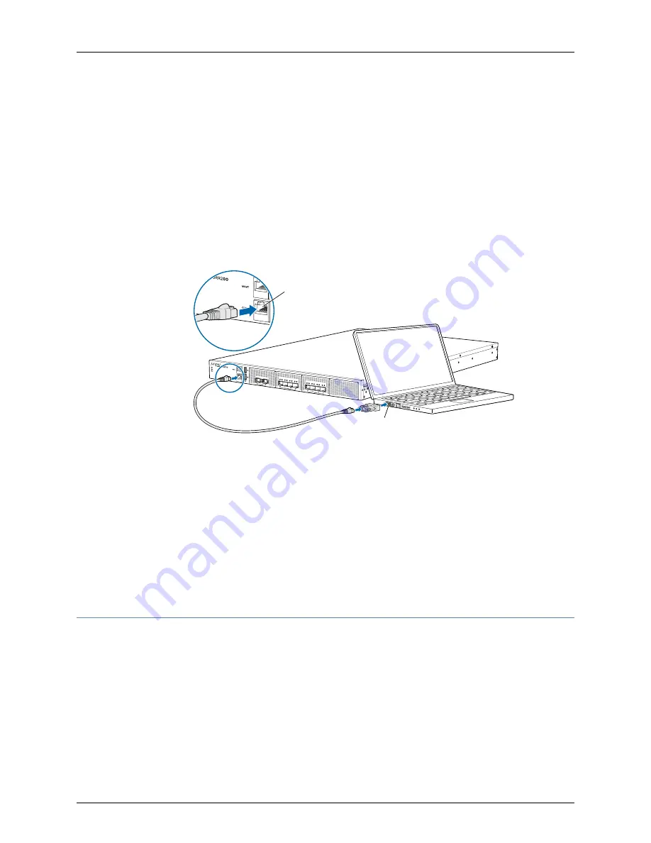
Connecting JRR200 Route Reflector to Management Devices
To configure the JRR200 route reflector, you must connect a management device to the
CONSOLE
port located on the front panel of the JRR200 route reflector, using the provided
RJ-45-to-DB-9 adapter and the RJ45 cable.
1.
Attach an electrostatic discharge (ESD) grounding strap to your bare wrist, and connect
the strap to the ESD point on the chassis.
2.
Plug one end of the RJ-45 cable into the
CONSOLE
port of the JRR200 route reflector
and the other end into the DB-9 serial port adapter.
g100086
Con sole port
RJ-4 5 cab le
Serial port
3.
Connect the DB-9 serial port adapter end of the RJ-45 cable to the serial port of your
management device. Use the following values to configure the serial port:
•
Baud rate—9600
•
Parity—N
•
Data bits—8
•
Stop bits—1
•
Flow control—None
Performing the Initial Configuration for JRR200
•
JRR200 Route Reflector Initial Configuration Using the CLI on page 49
•
JRR200 Route Reflector Factory-Default Settings on page 50
•
Viewing Factory-Default Settings of JRR200 Route Reflector on page 52
Copyright © 2018, Juniper Networks, Inc.
48
JRR200 Route Reflector Hardware Guide
Содержание JRR200
Страница 1: ...JRR200 Route Reflector Hardware Guide Modified 2018 08 15 Copyright 2018 Juniper Networks Inc...
Страница 8: ...Copyright 2018 Juniper Networks Inc viii JRR200 Route Reflector Hardware Guide...
Страница 10: ...Copyright 2018 Juniper Networks Inc x JRR200 Route Reflector Hardware Guide...
Страница 16: ...Copyright 2018 Juniper Networks Inc xvi JRR200 Route Reflector Hardware Guide...
Страница 28: ...Copyright 2018 Juniper Networks Inc 28 JRR200 Route Reflector Hardware Guide...
Страница 38: ...Copyright 2018 Juniper Networks Inc 38 JRR200 Route Reflector Hardware Guide...
Страница 64: ...Copyright 2018 Juniper Networks Inc 64 JRR200 Route Reflector Hardware Guide...
Страница 74: ...Copyright 2018 Juniper Networks Inc 74 JRR200 Route Reflector Hardware Guide...


